Module Descriptions, RFL 9508D Digital Section
8.9
TEST PANEL
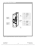
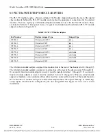
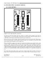
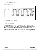
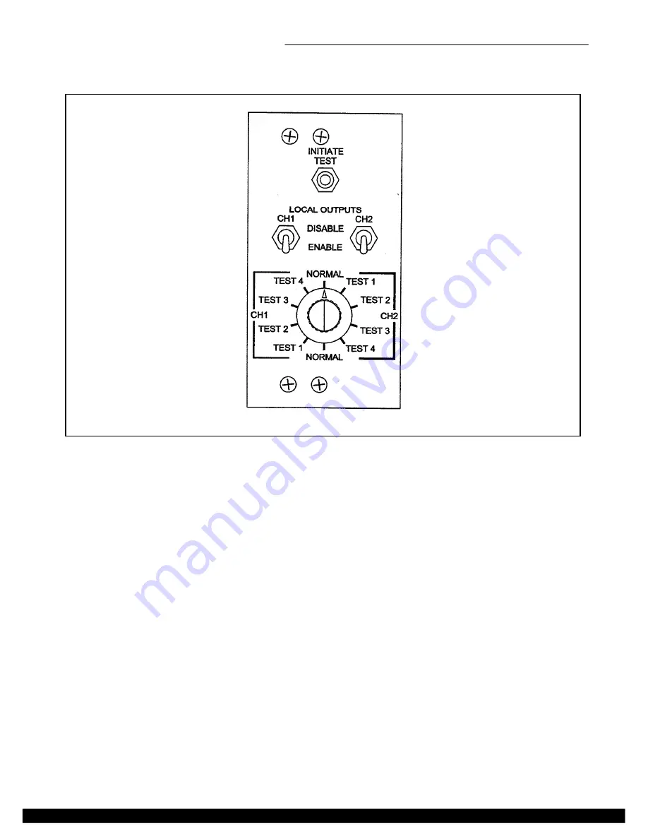
Figure 8-16. RFL 9508D Test Panel
The Test Panel is used to test all circuits related to the Transfer Trip function, at both ends of the
9508D system. It does this by sending a “test trip command” from the 9508D at the near end, to the
9508D at the far end, where an observer can verify the reception of the trip command by looking at
LEDs on the PLC-TT front panel, or by using NMS or SOE. The Test panel is only installed when a
PLC-TT module is installed. The Test Panel has an eight conductor cable which plugs into JP1 of the
PLC-TT module.
When the Test Panel is not in test mode, the rotary switch must be in the NORMAL position, and the
toggle switch must be in the ENABLE position. To perform a test, the operator must place the rotary
switch to TEST 1 position, for Transfer Trip function 1, and the toggle switch to DISABLE position, to
disable local outputs. The INITIATE TEST pushbutton is then pressed. An observer at the far end can
observe the LED for Transfer Trip function 1. The rotary switch can then be placed in positions 2, 3,
and 4 to test Transfer Trip functions 2, 3 and 4 of the PLC-TT module.
RFL 9508D UCC
RFL Electronics Inc.
March 11, 2010
8-37
(973) 334-3100

