Configuration
Section 5.
CONFIGURATION
5.1
INTRODUCTION
This section describes the procedure required to put the RFL 9508D system into service in the field. It
is assumed that the installation procedures described in Section 3 of this manual have been performed,
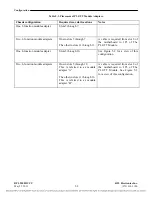
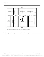
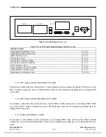
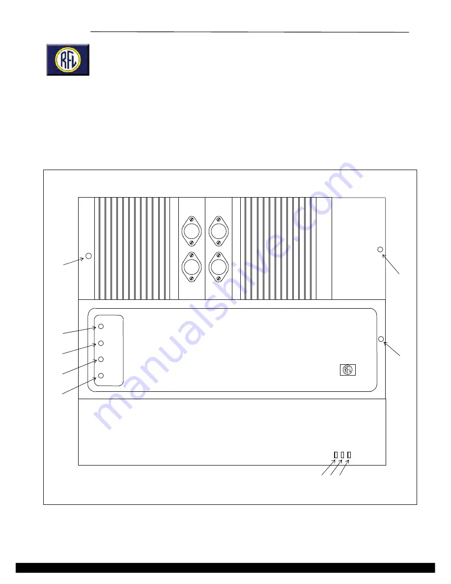
and the 9508D chassis are in place. Figure 5-1 shows the location of the RFL 9508D front panel
controls and indicators. Table 5-1 describes the functions of the controls and indicators.
8 9 10
RFL 9508D
PACKETIZING MUX
6
7
1
2
3
4
5
RFL 9508D
RF CHASSIS
POWER
NORMAL
ALERT
ALARM
RFL 9508D
AF CHASSIS
RFL Electronics Inc.
Figure 5-1. Front View Of RFL 9508D Chassis Showing Controls And Indicators
RFL 9508D UCC
RFL Electronics Inc.
May 27, 2011
5-1
(973) 334-3100

