9.5
MODULE PLACEMENT IN THE RF CHASSIS (100W SYSTEMS)
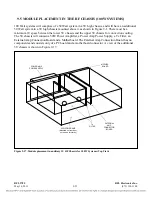
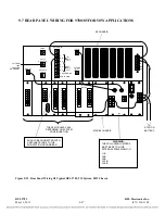
100 Watt systems will comprise of a 50 Watt system in a 3U high chassis, and will have an additional
50 Watt system in a 3U high chassis mounted above it as shown in Figure 9-1. There must be a
minimum 1U space between the lower 3U chassis and the upper 3U chassis for convection cooling.
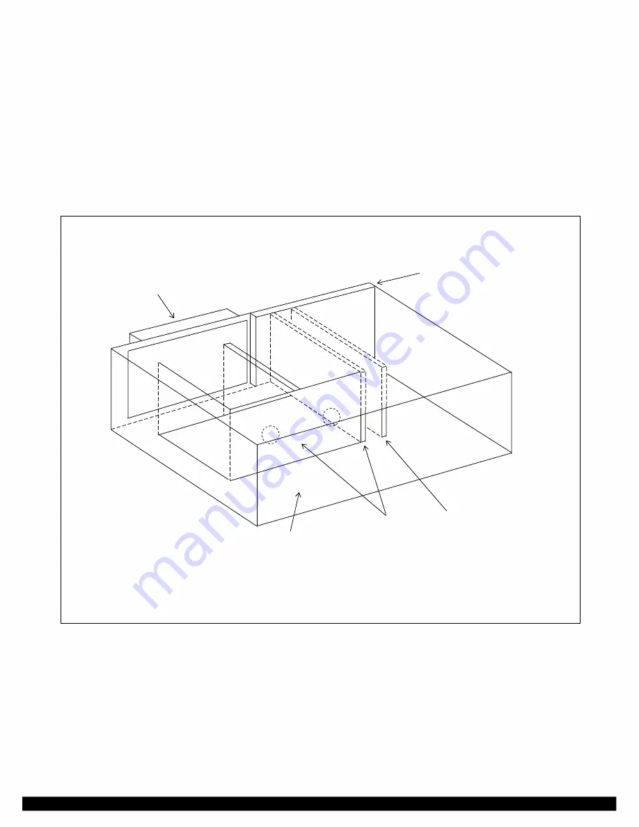
The 3U chassis will contain a 50W Power Amplifier, a Power Amp Power Supply, a Tx Filter, an
External Amp Connection Board and a Motherboard. The External Amp Connection Board has no
components and consists only of a PC board and a motherboard connector. A view of the additional
3U chassis is shown in Figure 9-17.
EXTERNAL
AMP
CONNECTOR
BOARD
TX
FILTER
POWER AMP
POWER SUPPLY
MOTHER
BOARD
50W POWER AMP
(Mounted on front door,
not shown for clarity)
Figure 9-17. Module placement in auxiliary 3U RF Chassis for 100W Systems (Top View)
RFL 9785
RFL Electronics Inc.
May 16, 2011
9-23
(973) 334-3100

