10.3
THEORY OF OPERATION
RFL 9785 Output Filters are elliptical six-pole passive L-C filters, that present less than 0.075 dB of
attenuation to frequencies within their passband. They are designed to have the greatest attenuation at
approximately the third harmonic of the lowest frequency in the passband. These frequencies are listed
in Table 10-2 as the "Approximate frequency of greatest attenuation" and will be attenuated by at least
55 dB. Signals between this frequency and 2 mHz will be at least 45 dB below the passband level.
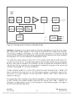
Output filters 106530-11 through -15 have additional circuitry to sense the impedance mismatch to the
load. A low impedance detection circuit is inserted between the filter output and the transmit output,
which may drive the load directly, or through hybrids. The detected signals are processed to calculate
the value of the reflected power. If a balanced hybrid is used between the transmitter output and the
load, the calculations can transform the results to display the value of the equivalent reflected power at
the load, with reduced accuracy.
The reflected power can be read using APRIL after a physical connection has been made and
communication is established between the RFL 9785 and a PC using the front or rear RS-232 ports.
Refer to Section 16 for additional information.
10.4
CONTROLS AND INDICATORS
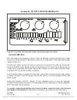
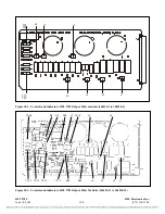
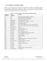
The RFL 9785 Output Filter Modules 106530-1, -2, -3, -5, -11, -12, -13, and -15 each contain seven,
three position jumpers. The 106530-4 and -14 modules do not have jumpers. The jumpers are used to
select the desired passband frequency from within the filters overall span. Note that all seven jumpers
(J1 through J7) must be installed in the same position for the filter to function properly. Table 10-2
shows the passband and the approximate frequency of greatest attenuation for each jumper position for
the filter modules.
RFL 9785
RFL Electronics Inc.
June 18, 2009
10-3
(973) 334-3100


