11.4
CONTROLS AND INDICATORS
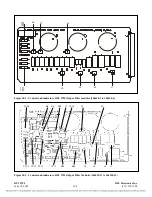
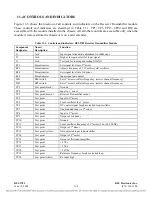
Figure 11-3 shows the location of all controls and indicators on the Receiver Downshifter module.
These controls and indicators are described in Table 11-1. TP1, TP3, TP13, TP20 and R69 are
accessible with the module installed in the chassis. All all other controls are accessible only when the
module is removed from the chassis or is on a card extender.
Table 11-1. Controls and indicators, RFL9785 Receiver Downshifter Module
Component
Name/
Function
Designator
Description
J1
Jack
Input signal attenuation adjustment in 10dB steps
J2
Jack
High or low gain select for input signal
J3
Jack
Test jack for loading and testing XILINX
RFL 9785
RFL Electronics Inc.
R10
Potentiometer
Sets signal level into 2
nd
mixer
R15
Potentiometer
Adjusts frequency of 5.12 mHz crystal oscillator
R28
Potentiometer
Sets signal level into 3rd mixer
R69
Potentiometer
Input signal gain adjust
SW1
DIP switch
Sets 1
st
mixer oscillator frequency (selects channel frequency)
SW2
DIP switch
Sets 1
st
mixer oscillator frequency (selects channel frequency)
TP1
Test point (black)
Ground
TP2
Test point
Input to 1
st
mixer
TP3
Test point (brown)
Receiver Downshifter output
TP4
Test point
Input to 2
nd
mixer
TP5
Test point
Local oscillator for 1
st
mixer
TP6
Test point
DC control signal for phase locked loop oscillator
TP7
Test point
Unattenuated input to 3
rd
mixer
TP8
Test point
Input to 3
rd
mixer
TP9
Test point
Output of 3rd mixer
TP10 Test
point Ground
TP11
Test point
Local oscillator frequency of 3
rd
mixer (26 or 26.25 kHz)
TP12
Test point
Output of 1
st
mixer
TP13
Test point (yellow)
Gain adjusted input to downshifter
TP14
Test point
Output of 2
nd
mixer
TP15
Test point
Output of first input amplifier
TP16
Test point
+ 8Vdc
TP17
Test point
+ 5Vdc
TP18
Test point
+ 10Vdc
TP19
Test point
Reference frequency for phase locked loop
TP20
Test point (white)
Rx input high
June 18, 2009
11-5
(973) 334-3100

