NOTE
THE ACTIVE FILTER FORMED BY U8 AND U9 IS TIGHTLY TUNED AT RFL.
NONE OF THE PARTS WITHIN THIS CIRCUIT ARE FIELD REPLACEABLE.
ANY COMPONENT CHANGES OR ADJUSTMENTS MADE TO THIS CIRCUIT
WILL DEGRADE SYSTEM PERFORMANCE.
12.3.2
SIGNAL LEVEL MONITOR
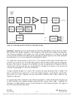
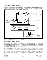
The signal passed by the narrowband filter is fed to operational amplifier U3B, which serves as a
buffer. The output of this buffer is passed through edge connector terminal C16 to the RFL 9785
Limiter Slicer module for further processing. It is also fed to a precision rectifier and averager formed
from operational amplifiers U1A and U1B, and their associated components.
The output of the rectifier is amplified by operational amplifier U1C, and is then applied to operational
amplifier U1D, which serves as a comparator. Potentiometer R26 sets the gain for U1D.
12.3.3
CARRIER LEVEL INDICATOR
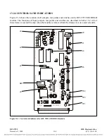
The digital panel meter (DPM1) is used to provide a visual indication of any signal level deviations
from normal, expressed in dB. Dual transistor Q1 and operational amplifiers U5A and U5B form a
logarithmic amplifier to convert the received signal strength to dB. R37 is used to temperature
compensate the log amp.
The output of the log amp is a 0 to -5 Vdc signal. Op amp U2A is used to invert, scale, and offset this
signal to convert it to a
±
1.0 Vdc signal (corresponding to
±
10 dB). This signal is scaled down to
±
100mVdc to drive the front panel meter DPM1.
When an external
±
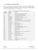
1.0 Vdc meter is used, jumper J3 must be in the “A” position. The
±
1.0 Vdc signal
out of U2A will then be buffered by U2B and sent out to pin A19. The external meter return is
connected to pin C19. Plus or minus 1.0 Vdc corresponds to
±
10.0 dB (0 volts represents 0 dB).
When an external 0 to -100
μ
A meter is used, jumper J3 must be in the “B” position. This sends the
output of the log amplifier through R54 and out on pin A19. The external meter return is connected to
pin C19. Zero
μ
A corresponds to –10.0 dB, 50
μ
A to 0 dB, and 100
μ
A to +10 dB.
When an external 0 to -5 Vdc meter is used, jumper J3 must be in the “C” position. This sends the
output of the log amplifier (U5B) directly to pin A19. The external meter return is connected to pin
C19. Zero Vdc corresponds to -10.0 dB, -2.5 Vdc corresponds to 0 dB, and -5 Vdc corresponds to +10
dB.
RFL 9785
RFL Electronics Inc.
July 7, 2006
12-4
(973) 334-3100


