Section 15.
VOICE MODULE
R80
R1
P1
C1
C37
C50
C58
C11
C7
C3
TP1
U1
R7
CR2
CR13
C6
C41
Q1
LCR1
U3
J1
U7
L1
U9
DS2
U10
U12
R2
R3
R4
R6
R5
R8
R9
R10
R11
R12
R13
R14
R16
R15
R18
R17
R19
R20
R25
R22
R30
R32
R31
R33
R27
R28
R23
R26
R24
R29
R3
4
R37
R35
R36
R42
R38
R41
R40
R39
R45
R43
R44
R46
R113
R114
R21
R4
8
R49
R4
7
R50
R78
R79
R81
R82
R85
R84
R53
R55
R54
R56
R77
R83
R51
R88
R52
R86
R87
R89
R57
R58
R59
R60
R61
R62
R70
R72
R74
R73
R75
R76
R68
R67
R65
R69
R64
R66
R121
R122
R107
R108
R
110
R90
R106
R105
R104
R111
R112
R101
R102
R103
R115
R99
R98
R97
R95
R94
R92
R93
R96
R91
R116
R117
R118
R119
R120
R109
C2
C5
9
C5
C4
C14
C13
C9
C8
C18
C20
C36
C26
C29
C44
C5
2
C5
3
C47
C51
C6
4
C60
C61
C15
C12
C10
C19
C55
C22
C2
4
C2
3
C2
5
R125
C39
C40
C42
C43
C38
C45
C32
C31
C57
C56
C65
R124
C62
C63
C17
C16
C34
C27
C28
C30
C33
C35
C49
C48
TP2
TP3
TP4
TP8
TP5
TP6
TP7
U4
U5
R63
R71
CR1
CR3
CR4
CR20
CR6
CR5
CR9
CR11
CR7
CR10
CR8
CR12
CR18
CR19
CR17
CR15
CR16
CR14
CR2
1
CR22
CR2
3
Q2
Q3
Q5
U2
J2
J3
U8
U6
U11
C54
DS1
SP1
J5
J4
R123
C21
Q4
C4
6
TONE
ADJ
97-VOICE ECB NO. 106568 REV D
1999 RFL ELECTRONICS INC., BOONTON, NJ, U.S.A.
VO
IC
E EN
32
1
C
A
IN
AGC
RE
C CA
LL
IN
OUT
DIS
EN
EXT
INT
IN
OUT
%MOD
SIDETONE
NORM
TEST
AUDIO
LEVEL
DE
T
VO
IC
E
TO
N
E
LEVEL
MOD
AGC OUT
LEVEL
CO
M
OU
T
A
UDI
O
+
+
+
+
+
+
+
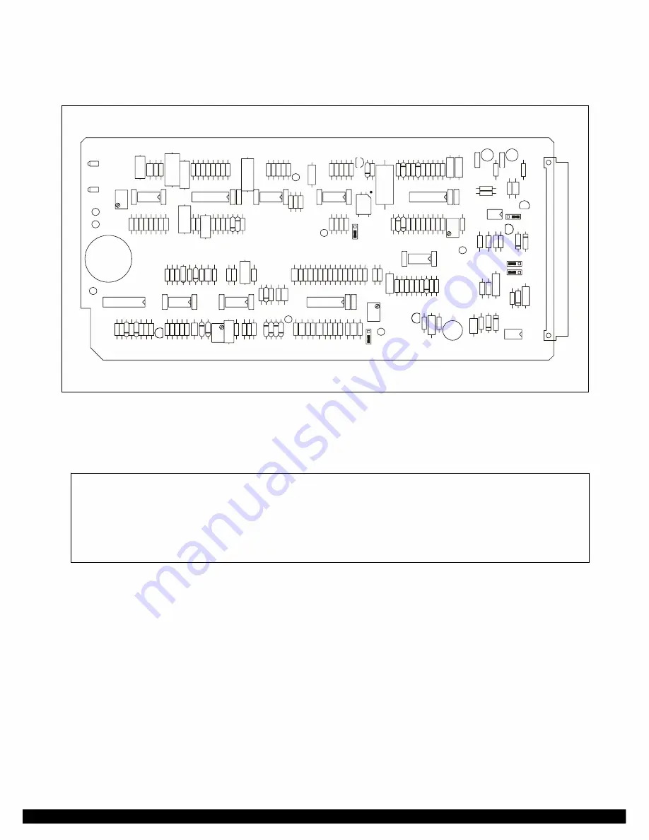
Figure 15-1. RFL 9785 Voice Module
15.1
DESCRIPTION
NOTE
Throughout this section, signal names appear in CAPITAL letters. Inverted or active-low
signals appear in CAPITAL letters followed by an asterisk (RESERVE*). IC pin numbers
are indicated by the device circuit symbol followed by a dash and the pin number (U1-1,
U1-2, etc).
The optional RFL 9785 Voice Module (Fig. 15-1) contains a voice transmitter, a signaling tone
oscillator, a signaling tone detector, and a voice receiver. When the RFL 9785 terminals at both ends
of a protected line are equipped with voice modules and the other components that comprise the voice
option, two-way voice communications can occur between the stations without the need for a
telephone hook-up. The voice signals will be injected onto the powerline carrier.
The voice option is made up of three main components. These are a voice module, a voice filter
(Figure 15-7), and a handset. When the voice option is used, the voice module is plugged into the
appropriate slot in the front of the RFL 9785 chassis. In addition to this the voice filter must be
plugged into the Receiver Detector module (see Section 12), and the handset must be plugged into the
front of the RFL 9785 front panel or hard wired to the rear of the chassis.
RFL 9785
RFL Electronics Inc.
April 25, 2005
15-1
(973) 334-3100

