+
+
-
-
Block
Output #1
{
{
106635-1
TB3-1
TB3-2
TB3-3
TB3-4
TB4-5
TB4-6
TB4-7
Block
Relay #1
FSVM Set To:
Carrier Freq.
Wht (TP-20) +
Blk (TP-1) -
Measure Level,
set J1 and J2 per Table 4-3 in this Manual
RS-232
SOE
SOE I/O
IRIG B
SOE
RS-232
On Front
Door
106480
106475-2
All Contacts are shown Unenergized
Block
Output #2
RX DET
106515-X
106435-1
TB5-6
TB5-7
TB5-5
Block
Relay #2
Checkback
106525
DNSH
106575
Part of SS
Input I/O
106435-1
Part of 9785
SS I/O
106635-1
Protector
J7
J16
W8
TB9-5
TB9-6
J7
RX In
75
50
106595
J3
J2-1
J2-2
+
-
TB9-7
TB9-8
+/- 1VDC
W3
W5
{
Ext
Meter
Part of AM
Logic Front
Door LEDs
RX Det
Blk Out
106540
+
-
ISO
Input
TB5-3
TB5-4
{
RMT
Int
To/From
CkBk Aux
Chassis
when
supplied
Block
Received
Block
Received
Block
Received
Block
Received
1
2
FSVM Set To:
Carrier Freq.
Yel (TP-13) +
Blk (TP-1) -
Adjust Gain (R69),
for 200mV with Remote TX Keyed ON
J3 should be set to 'Out' if W3 - W5
is installed. If W3 - W5 is not
installed then J3 is installed per line
impedance to the receiver closest
to the line.
Note 50 and 75 Max.
1 W Use. External
Resistors when Receiver
Power is Greater than 1W
Measure DC Voltmeter
3.16VDC
Yel. TP-5 +
Blk. TP-1 -
Observe Front Door Meter
Receive Level for 0dB
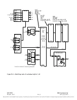
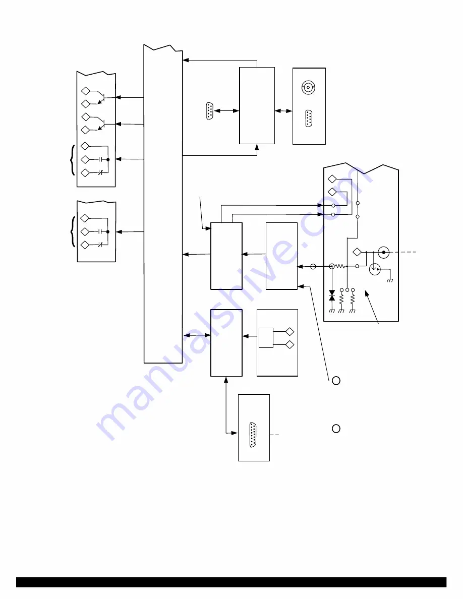
Figure 22-15. Block Diagram for Troubleshooting Part 2 of 2
RFL 9785
RFL Electronics Inc
.
March 1, 2013
22-
17
(973) 334-3100

