RFL 9785
RFL Electronics Inc.
June 18, 2009
2-10
(973) 334-3100
2.7.14
CHASSIS
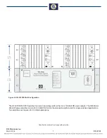
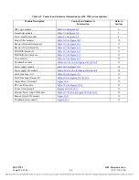
The RFL 9785 chassis houses the power supply(s), processing modules, and I/O modules. All
interconnections between modules is accomplished using a system motherboard. Some RF signals are
routed with coax cables. Additional information on the RFL 9785 Chassis and Motherboard can be
found in
of this manual.
2.7.15
CHECKBACK ALARM CHASSIS
The optional RFL 9785 Checkback Alarm Chassis allows a user to determine the status of each of the
eight checkback tests by means of a relay contact closure. Additional information on the RFL 9785
Checkback Alarm Chassis can be found in
of this manual.
2.7.16
ACCESSORY EQUIPMENT
Other circuit card modules and assemblies are available to enhance the operation of the RFL 9785
terminal, or to adapt it to special applications. If any accessory equipment was furnished with your
system, Instruction Data Sheets for each item will appear in Section 24 of this manual.
2.8
SYSTEM THEORY OF OPERATION
The RFL 9785 has four functional blocks: the transmitter section, the receiver section, the logic and
control functions, and the sequence of events functions. All of these functions are tied together by the
chassis and motherboard and are powered by the power supply. A typical block diagram of the RFL
9785 is shown in Figure 2-2.
2.8.1
TRANSMITTER SECTION
The function of the transmitter section is to provide the desired carrier frequency, at the desired power
level at the transmitter port when commanded. The transmitter consists of three basic modules, the
Transmitter Module, the Power Amplifier Module, and the Output Filter Module. The Transmitter
Module generates a clean, precise, carrier at the desired frequency and at a given power level.
The transmitter may be instructed to generate one of three carrier levels which correspond to 1, 3, and
10 watts of transmitted power after the Power Amplifier. Normally the RFL 9785 is configured to
transmit at a nominal 10W power level. See Section 7 for more information about the Transmitter
Module.
The output of the Transmitter Module is fed into the Power Amplifier Module. The Power Amplifier is
the only rear-mounted module other than I/O modules. The Power Amplifier boosts both the voltage
and current to provide the specified 10 watts of transmit power.
The Power Amplifier also contains a circuit which detects a loss of transmit carrier. This is used to
indicate a failure of the transmit circuits. Additionally, the Power Amplifier uses advanced feedback
techniques to emulate the desired 50 ohm output impedance. Not only does this increase the inherent
efficiency of the amplifier, but allows for the output impedance to be adjustable to match the actual
impedance of the line. See Section 8 for more information about the Power Amplifier Module.
In order to remove any unwanted harmonics from the amplified carrier signal, the output of the Power
Amplifier is followed by the Output Filter. The Output Filter is a passive bandpass filter. In order to
avoid having to make detailed adjustments to the filter or, worse, risking poor impedance matching at


