4.4
POWER SUPPLY CONSIDERATIONS
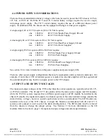
There are three standard station battery voltages which can be used to power the 9785 chassis: 48 Vdc,
125 Vdc, or 250 Vdc. Both the 48 V and 125 V station battery voltages require the use of a single,
wide-range power supply. The 250 V station battery requires the use of a different chassis power
supply. In addition to this, the chassis can be equipped with single or dual power supplies.
A single supply 48 or 125 Vdc system (38 to 150 Vdc) requires:
one
106455-1
48/125 Vdc Single Power Supply I/O and
one
106535-1
48/125 Vdc Power Supply.
A dual supply 48 or 125 Vdc system (38 to 150 Vdc) requires:
one
106455-3
48/125 Vdc Dual Power Supply I/O and
two
106535-1
48/125 Vdc Power Supplies.
A single supply 250 Vdc system (200 to 300 Vdc) requires:
one
106455-2
250 Vdc Single Power Supply I/O and
one
106535-2
250 Vdc Power Supply.
A dual supply 250 Vdc system (200 to 300 Vdc) requires:
one
106455-4
250 Vdc Dual Power Supply I/O and
two
106535-2
250 Vdc Power Supplies.
See section 16 for more information on the power supplies and power supply I/Os.
There are other power supply configurations that may be appropriate under certain circumstances. For
example, if more than 10 W of transmit power is required, an external amplifier will be required and
the external amplifier may be able to supply power to the 9785 chassis.
4.5
INPUT AND OUTPUT VOLTAGES
The input and output voltages of the 9785 (other than the carrier signals) are typically either 48, 125,
or 250 Vdc nominal. The 48 and 125 Vdc systems utilize the same power supply and I/O modules,
while the 250 Vdc system requires that a different power supply and I/O module be installed in the
chassis. Normally, the inputs and outputs in a chassis operate at the same nominal voltage (usually the
station battery voltage), however, special applications can be accommodated. The I/O Modules are
installed in the rear of the 9785 chassis. A single I/O Module accommodates both 48 and 125 V
systems, and a jumper is used to select the desired configuration. The I/O Module must be removed
from the chassis to change the jumper setting. See Section 19 for more information on the I/O
modules. Refer to Section 1, page 5 for input and output, voltage and current specifications.
RFL 9785
RFL Electronics Inc.
March 24, 2008
4-7
(973) 334-3100

