6.3.6
BLOCK OUTPUT CIRCUIT
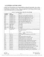
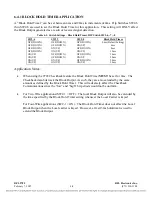
A block generated by the Block Control Logic will turn-on transistors which drive BLOCK-OUT-
RLY1, BLOCK-OUT-RLY2(optional), BLOCK-OUT-SS1, and BLOCK-OUT-SS2 outputs at edge
connector pins C20, B23, A22, and C23 respectively. These signals will energize solid-state and
electro-mechanical relays for the period of the block plus an additional 3ms hold time. The active
BLOCK-OUT-SS1 and BLOCK-OUT-SS2 outputs are 32Khz 50% duty-cycle signals. A BLOCK
indicator DS2 will illuminate to show that a block has been generated.
If an under-voltage condition is detected by the power supply, the POWER-FAIL (A17) and/or
POWERFAIL2 (C16) inputs to the 9785 AM Logic Module will be logic-low. Both signals in the
logic-low state will generate a logic-low POWER signal to prevent a BLOCK function for the period
of the under-voltage condition plus an additional 320ms.
The status of the block output circuit is monitored by the optional sequence of events module (SOE).
6.3.7
RECEIVE VOICE CONTROL LOGIC
If the voice option is installed, voice can be received when the receive carrier is detected from the
remote unit and the local carrier is not keyed. This implies that the SIG-COMP-IN signal is active and
the CARRIER-SWITCH signal is inactive. The voice will be muted if either of these conditions is not
met. The logic low VOICE-MUTE signal is applied to edge connector pin A27.
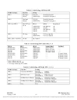
High or low voice level is selected with Switch SW2-2. Either a logic low VOICE-HIGH or VOICE-
LOW signal is produced depending on SW2-2. These outputs are applied to edge connector pins C27
and C25 respectively. A logic low VOICE-MUTE overrides VOICE-HIGH and VOICE-LOW signals.
RFL 9785
RFL Electronics Inc.
February 7, 2007
6-4
(973) 334-3100


