background image

602400011500 

Revision C 

Page 

9

 of 

24  


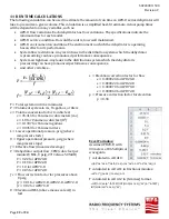
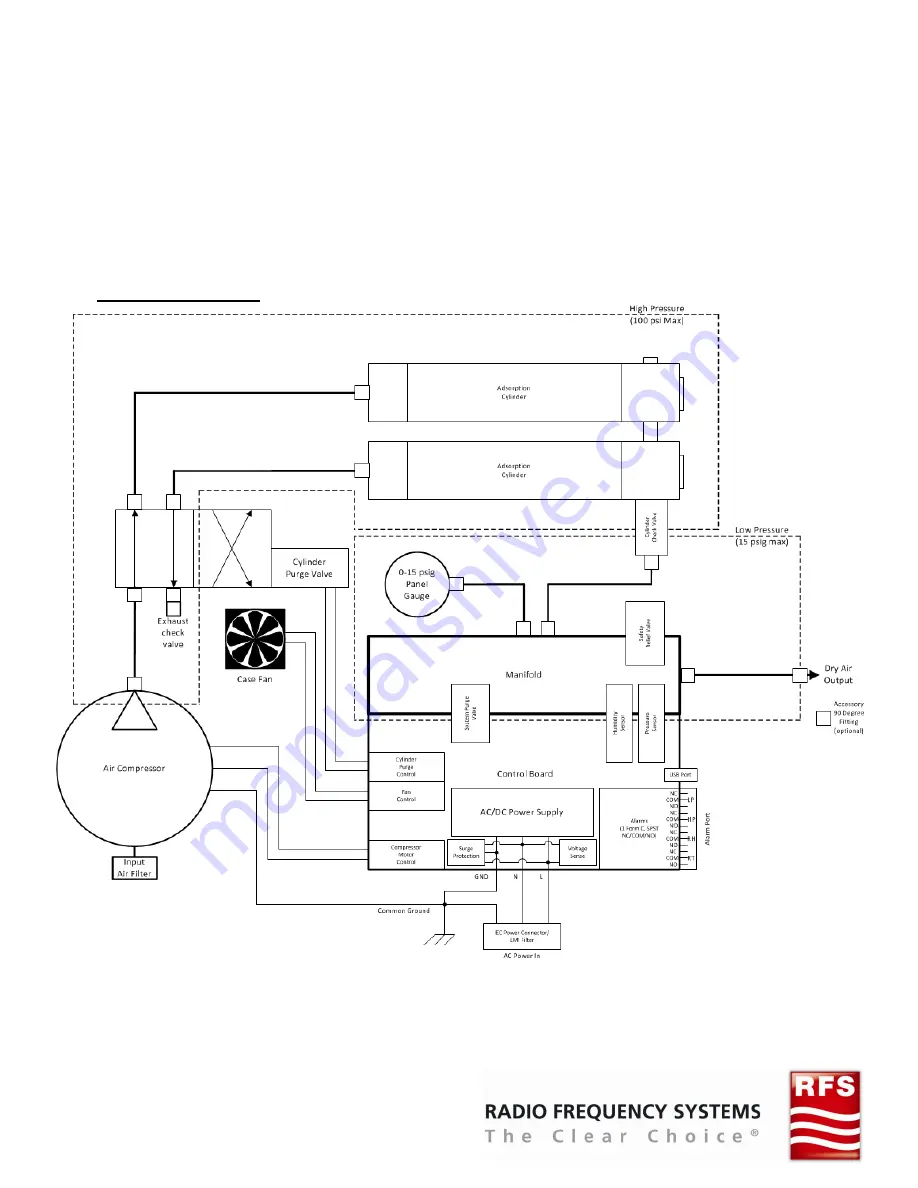
The  APD-D  series  dehydrators  are  fully 

automatic  when  energized.  The  system 
pressure is monitored in real-time during 

standby  operation.  When  the  system 
pressure  is  at  or  below  the  lower 

operational  pressure,  then  the  unit  will 
activate and re-pressurize the system with 

dry  air.  The  unit  will  return  to  standby 

operation  when  the  upper  operational 

pressure is reached. 
A dehydrator duty cycle of less than 5% is 

recommended. 

Maximum 

continuous 

active operation must not exceed 4 hours. 

Any  leaks  in  the  distribution  system 
should  be  small  enough  to  ensure  that 

active  operation  does  not  occur  more 
often than once every 48 hours (2 days). 
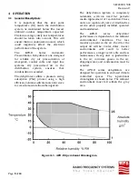
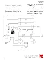
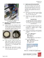
4.2


Detailed


Operation:


Figure 4.2 – System Diagram 


Summary of Contents for APD-D Series

Page 1: ...602400011500 Revision C Radio Frequency Systems 200 Pond View Drive Meriden CT 06450 Ph 203 630 3311 Fax 203 634 2272 www rfsworld com Product Manual AUTOMATIC PRESSURIZATION DEHYDRATOR APD D Series ...

Page 2: ...602400011500 Revision C Page 2 of 24 This Page Intentionally Left Blank ...

Page 3: ... TERMS DEFINITIONS 7 4 OPERATION 8 5 CONTROLS AND INDICATORS 12 6 MAINTENANCE 15 7 REPLACEMENT PARTS AND ACCESSORIES 18 8 OPTION CONFIGURATION SOFTWARE UPGRADE 18 9 SPECIFICATIONS 20 10 MODEL CONFIGURATION 21 11 RUN TIME CALCULATIONS 22 12 TRANSMISSION LINE VOLUMES 23 13 CE DECLARATION OF CONFORMITY 24 ...

Page 4: ...cted The APD D series dehydrators are designed for 120 230VAC use at 50 60Hz The AC Mains configuration must be 1 N PE meaning 3 conductors 1 1 Single phase Line power wire color black or brown 2 N Neutral phase return tied to Earth ground at the local power panel wire color blue or white 3 PE Protective Earth ground wire color green with yellow stripe or green ____________________________________...

Page 5: ...ydrator is designed for free standing operation on its vibration isolating rubber feet The dehydrator should be placed on a firm level surface An accessory wall rack mount shelf is available for alternative mounting methods and locations The APD series dehydrator requires a minimum of 2 clearance on the sides and top for proper heat dissipation 2 4 Installation Procedure 2 4 1 Ensure that the site...

Page 6: ...ve operation run time Possible Solution Run time to pressurize the distribution system may have been miscalculated Please recalculate the run time record the unit s model and serial numbers and contact RFS Support to reconfigure the run time alarm Symptom Run time exceeds 4 hours before distribution system reaches the configured upper operating pressure Possible Solution Check for leaks in the dis...

Page 7: ...herefore it is important to keep the dew point temperature of the air inside the waveguide or cable below the ambient temperature outside the waveguide or cable to avoid condensation 3 3 Dew Point Reduction Tdr is the reduction of the dew point temperature that results from the dehumidification process The larger the Tdr the more efficient the dehumidification process is 3 4 Distribution System is...

Page 8: ...gid line ir in the res that sure swing ng a high cular sieve put air 4 1 APD D Operation The deh automatic media rep units are service w and main The A performa environm moisture output ai environm performa maintena in the a dripping avoided The AP designed controlled climatogr environm area nal Climatog ydration s c with no placement capable of when proper ntained APD D ance is depe mental con pr...

Page 9: ... will activate and re pressurize the system with dry air The unit will return to standby operation when the upper operational pressure is reached A dehydrator duty cycle of less than 5 is recommended Maximum continuous active operation must not exceed 4 hours Any leaks in the distribution system should be small enough to ensure that active operation does not occur more often than once every 48 hou...

Page 10: ...lve will open to prevent an unsafe pressure condition The control board and the humidity and pressure sensors monitor the low pressure dry air output and adjust unit operation accordingly The system purge valve allows for periodic purge and repressurization of the waveguide or cable system This optional feature requires the humidity alarm option or system purge option to be installed and configure...

Page 11: ...he need to replace the desiccant cylinders The humidity sensor requires air flow for accurate measurement In order to accurately measure the system air humidity level humidity monitoring is only active during pumping and purging cycles For this reason the system purge option is required when the humidity alarm option is present 4 4 3 Run Time Alarm The optional run time alarm can be used as a warn...

Page 12: ...d COMPRESSOR yellow Illuminated when compressor is active and pressurized dry air is being supplied LOW PRESSURE red Illuminated when the system pressure has dropped below the low pressure alarm threshold HIGH PRESSURE red Illuminated when the system pressure has dropped below the low pressure alarm threshold This indicator is only active on models configured with the high pressure alarm option HU...

Page 13: ...y protruding To reset the circuit breaker wait for at least one minute after the overload occurred then press the button back in The unit will resume normal operation Picture 5 2 APD D Series Rear Panel Connections 5 5 AC Mains Voltage Input The IEC C14 type AC Mains voltage input connector is located in the lower right corner of the rear panel The APD20 D and APD70 D are supplied with a 2 meter N...

Page 14: ...ing air to the unit The fan is operational only when the unit is actively pumping At least 2 inches of clearance is required for proper cooling air flow 5 8 Alarm Port The alarm port allows for customer supplied remote monitoring equipment to monitor the dehydrator for configured alarms The alarms are provided using 1 Form C relays All alarm contacts are passive and power must be supplied external...

Page 15: ...s 54852BE and SitePro GL610 6 MAINTENANCE If properly installed and operated the Dehydrator will not require any maintenance for the length of the warranty period After that the only preventative maintenance requirements are a check of the compressor s input air filter element and dust debris removal once per year 6 1 Taking the Unit Out of Service and Removing the Lid 6 1 1 Disconnect the input p...

Page 16: ...placement the RTC date and time should be reset Refer to Picture 6 2 6 3 1 Remove the old battery by gently lifting the retaining clip The battery should slide out of the holder easily 6 3 2 Install the new battery by pushing it under the clip until it snaps into the holder ___________________________________________________________________________________________________ W A R N I N G The followi...

Page 17: ...tart normally 6 4 Replacing the Lid Placing the Unit Back In Service 6 4 1 Refer to Picture 6 1 and Picture 6 2 Place the lid next to the unit fan down Connect the case fan connector to the control board s fan header wires facing in 6 4 2 Pivot the lid onto the unit making sure not to pull or bind the fan wires 6 4 3 Replace the lid screws Insert all loosely at first and then torque each screw to ...

Page 18: ...Desiccant cylinder subassembly APD70 D APD72 D 18 30032091 Rubber bumper foot M6 stud All APD D Models 19 20041902 Site Ground Kit 6AWG crimp terminal All APD D Models 20 20040835 Wall Rack Mount shelf mounting hardware not included All APD D Models 21 10042341 Field Configuration Upgrade Kit All APD D Models 8 OPTION CONFIGURATION SOFTWARE UPGRADE The APD D Dehydrator can be upgraded in the field...

Page 19: ...mes to indicate successful firmware update 8 1 3 The unit will then restart normally indicators light top to bottom then extinguish bottom to top The USB device can now be removed 8 1 4 To verify the upgrade process plug the upgrade USB device into a PC and open the UPDATE LOG file on the USB device The following is a sample of the file contents Picture 8 1 UPDATE LOG File a The log indicates succ...

Page 20: ...1A Low Pressure Alarm Standard on all units Standard configurations Fixed at 0 5 psi 3 4 kPa below lower operational pressure Low Pressure configurations Fixed at 0 25 psig 1 7 kPa SIZE AND WEIGHT Dimensions H x W x D inches mm 9 5 x 13 5 x 9 5 242 x 343 x 242 Net Weight pounds kilograms 25 11 4 30 13 6 ENVIRONMENTAL Max Operational Altitude 5 psig feet meters 6 500 1 930 6 000 1 830 12 400 3 780 ...

Page 21: ...602400011500 Revision C Page 21 of 24 10 MODEL CONFIGURATION ...

Page 22: ...run time in minutes Volume of system in m3 ft3 gallons or liters Volume conversion factor to cubic feet 35 314 for Volume in cubic meters m3 1 0 for Volume in cubic feet ft3 0 1337 for Volume in gallons 0 0353 for Volume in liters Lower operational pressure psig where compressor starts Upper operational pressure psig where compressor stops Effective flow linearized average Dehydrator output flow C...

Page 23: ...0 16 0 432 Commscope Andrew Elliptical Waveguide volumes Waveguide Type Liters per meter l m Cubic foot per foot ft3 ft EW17 6 60 0 0710 EW20 5 62 0 0605 EW37 1 96 0 0211 EW43 1 69 0 0182 EW52 1 045 0 0112 EW63 0 855 0 0092 EW64 0 725 0 0078 EW77 0 585 0 0063 EW85 0 39 0 0042 EW90 0 334 0 0036 EW127A 0 25 0 0027 EW132 137 0 167 0 0018 EW132 140 0 167 0 0018 EW132 144 0 167 0 0018 EIA Rectangular W...

Page 24: ...Page 13 e 24 of 24 CE DECLA ARATION OF CONF FORMITY 60 02400011500 Revision C 0 C ...

Reviews: