


DTR_314-05-01-001_EN_a
11
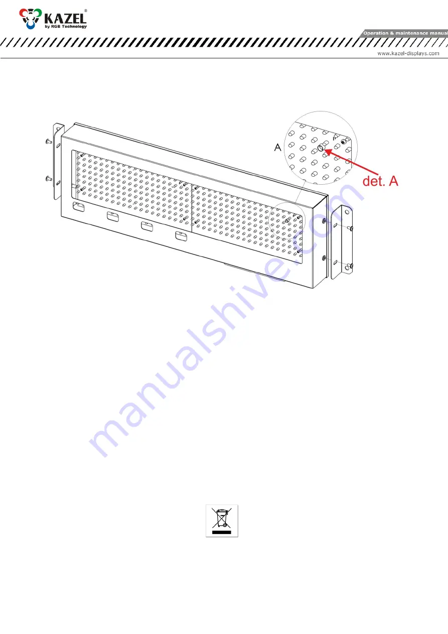
7.
Automatic brightness control of the remote display
RM-470 has a brightness sensor installed on the LED panel as standard. When the automatic control profile is
enabled, the device adjusts its brightness responsively to the intensity of daylight.
det. A – brightness sensor
Fig. 11
8.
Initial start-up
Step 1: Make sure that all cables are properly connected,
Step 2: Make sure that all components have been installed in the correct orientation,
Step 3: Connect the device to the mains power supply,
Step 4: The properly connected display will show moving arrows (> >> >>>), followed by a hard space symbol (_)
in the bottom right corner. It means that the user has 7 seconds to send the configuration to the remote
display. If no configuration is sent to the device, it will launch the "Autolearn" process.
9.
Disposal and recycling
9.1
Packaging material recycling
The packaging elements must be segregated and recycled in accordance with the local waste disposal
regulations.
9.2
Device disposal
The device must not be disposed of with normal municipal waste! In accordance with Directive 2012/19/EU
(WEEE), the user is obliged to deliver the damaged or destroyed device to the appropriate disposal facility if
there is no economically justified repair possibility.
10.
Most common installation errors
1.
Invalid configuration uploaded to the remote display.
2.
Drilling additional mounting holes in the display's housing.


