


4
DTR_314-05-01-001_EN_a
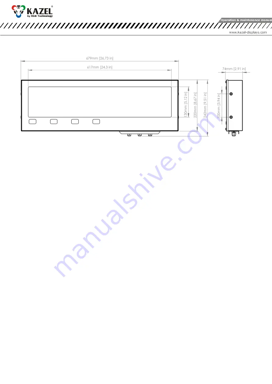
3.2
RM-470 dimensions
3.2.1
Dimensions without accessories
Fig. 2
4.
Device installation
The device should be mounted on a flat surface, with the wires facing down. Only the correct installation of the
device ensures its proper operation and the maintenance of the device parameters, such as housing tightness to
the declared IP class.
NOTICE!
Before any installation or maintenance operations, refer to the manual supplied by the manufacturer. Improper
connection to the mains power supply, incautious device installation, or improper use may cause property
damage, loss of health or death from an electric shock! In addition, failure to comply with the manufacturer's
instructions may void the warranty.
NOTICE!
It is forbidden to make any additional mounting points or any holes in the device components.
4.1
RM-470 application
RM-470 is designed to display measurement results transmitted by weighing terminals. The displays operate in
the automatic mode by default (see 4.2 "Autolearn”) and, in typical cases, they do not require prior
configuration. In special situations, it may be necessary to adjust the settings using RGB WagSet 2 software or
the Web-panel or through the user menu embedded in the device.
4.2
"Autolearn” function
The “Autolearn” mode is enabled by default (position #0 is set in the "proto" submenu). To disable it, the
communication protocol should be selected manually using the embedded user menu or RGB WagSet 2
software or the Web-panel. When this mode is active, at each start-up, the device detects the parameters of
communication with the weighing terminal and analyses the structure of the data frames which are sent to it. It
then adjusts its settings to allow proper communication with the terminal. The whole operation lasts a few
seconds, depending on the baud rate and time intervals between the consecutive frames. All communication
interfaces are supported, i.e. RS-232, RS-485/RS-422, 0/20mA digital current loop and the Ethernet.
The "Autolearn" procedure steps and their signalling are as follows:
1. Baud rate detection - dot 1 is flashing on the display,
2. Baud rate verification - dot 1 is solid, dot 2 is flashing,
3. Analysis of the protocol and its frame structure - dots 1 and 2 are solid, dot 3 is flashing.
During the analysis of the protocol and its frame structure, the measurement unit is also recognised, if sent by
indicator. The following tags are recognised - "kg" 'k' 'K' "tn" "TN" " t" 'T' 't' "LB" "lb" 'L' 'l' "OZ" "oz" 'o' 'O'. In
case the indicator does not send units or sends units that are not recognised by the “Autolearn” function, the
default unit will be set. Depending on the purchased regional version, it is "kg" or "lb".


