background image


DTR_314-05-01-001_EN_a


The “Autolearn” function also detects gross/net measurements if the following markers are sent in the frame:  
- for the Net measurement: 'n' and 'N' from the ASCII table, 
- for the Gross measurement: 'g' and 'G' from the ASCII table. 
In  this  case,  the  marker  position  will  also  be  saved.  If,  during  the  operation  of  the  device,  the  transmitted 
measurement marker changes, e.g. from "n" to "g", the indicator will change accordingly.  
The “Autolearn” function supports the following transmission parameters: 
 

Baud rate: 

2400, 4800, 9600, 19200 

Transmission  parameters  (data  bits,  parity,  stop 
bits): 8N1, 7E1, 7O1 

8N1, 7E1, 7O1 

Table 1 

4.3


 RM-470 manual configuration (Communication protocol selection)  

4.3.1


Embedded user menu (microswitch) 

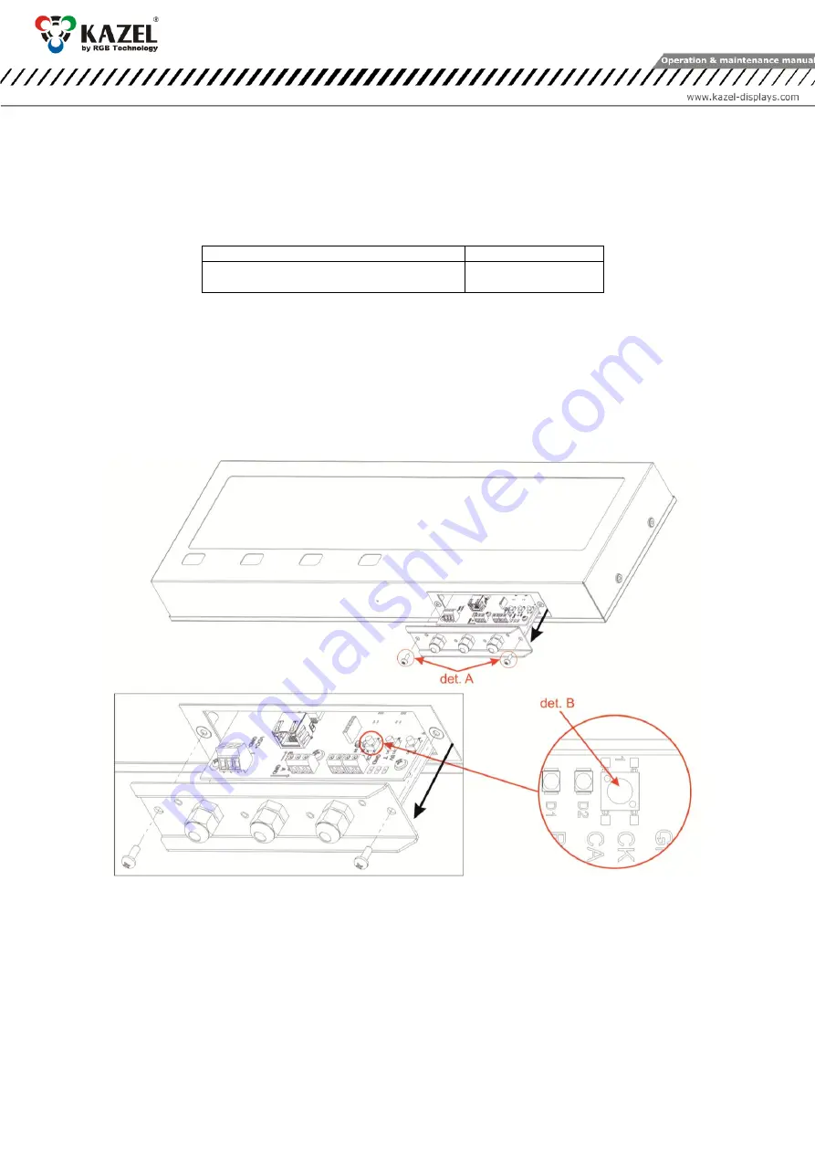
The user menu embedded in the device allows to select  the communication protocol, display the information 
about  the  software  version,  reset  to  the  default  settings.  The  "B1"  microswitch,  used  to  operate  the  menu, 
is located  inside  the  display,  and  is  accessible  after  unscrewing  two  screws  M4x10  (Fig.  3,  det.  A)  and  after 
pulling out  the drawer as indicated by the  black  arrow.  The microswitch is  located on the  controller  board  as 
illustrated below (Fig. 3, det. B). There is no need to open the external covers.  


det. A

 – Screw M4x10; 

det. B

 – microswitch 

Fig. 3 


The  user  menu  is  called  up  by  pressing  and  holding  down  the  "B1"  microswitch  and  releasing  it  
 when  the  desired  option  is  displayed.  Regardless  the  option,  you  can  exit  the  user  menu  by  pressing  the 
microbutton  and  releasing  it  when  switching  between  the  options  (while  switching  between  the  options,  the 
display is not displaying any information) 

The user menu has the following options: 

1)


info  -  This  option  allows  you  to  display  the  software  version.  For  displays  with  the  Ethernet  interface, 
network layer settings are also provided (IP address, network mask, communication port for RGB WagSet 2 
software  and  communication  port  for  the  weighing  indicator).  Exiting  the  "info"  submenu  happens 
automatically after displaying the information. 

Summary of Contents for 314-05-01

Page 1: ...OPERATION AND MAINTENANCE MANUAL RM 470 Product code 314 05 01 Explanatory figure OPERATION AND MAINTENANCE MANUAL RM 470 Product code 314 05 01...

Page 2: ...rates 6 4 3 3 RGB WagSet 2 software 6 4 3 4 Web panel 7 5 Display controller board 7 5 1 Connectors and buttons on the controller board 7 5 2 List of connectors of the display controller board 8 5 2 1...

Page 3: ...during transportation It is forbidden to transport the device components separately in a collective package each item must be packed individually and cannot hit one another during transportation The...

Page 4: ...e device 4 2 Autolearn function The Autolearn mode is enabled by default position 0 is set in the proto submenu To disable it the communication protocol should be selected manually using the embedded...

Page 5: ...oswitch used to operate the menu is located inside the display and is accessible after unscrewing two screws M4x10 Fig 3 det A and after pulling out the drawer as indicated by the black arrow The micr...

Page 6: ...t 2 software 2101 and communication port for the weighing terminal 2102 To restore the default settings you should during the normal operation of the device press the microbutton and hold it down unti...

Page 7: ...er board The controller board is responsible for processing and displaying the weighing result incoming from the weighing indicator 5 1 Connectors and buttons on the controller board det A LED module...

Page 8: ...ARD 4 Interface Function Connector markings Notes RS 232 RA The RXD line of the RS 232 interface should be connected with the weighing indicator TXD output RK GND line of the RS 232 interface 0 20mA C...

Page 9: ...2 software via RS 485 RS 422 connector 5 2 3 0 20mA digital current loop For configuration purposes the user connects the remote display to the computer with installed RGB WagSet 2 software via digita...

Page 10: ...ls Fig 8 Fig 9 6 3 Mounting brackets Fig 10 Pole mounting brackets are available in the following sizes 2 pole outer diameter 60 3 mm 3 pole outer diameter 84 0 88 9 mm 4 pole outer diameter 111 1 115...

Page 11: ...bol _ in the bottom right corner It means that the user has 7 seconds to send the configuration to the remote display If no configuration is sent to the device it will launch the Autolearn process 9 D...

Reviews: