6
DTR_319-01-01-001_EN_b
The user menu has the following options:
1)
i (info) - This option allows you to display the software version and returns the information about the set
communication protocol. Exiting the info option is done automatically after displaying the information.
2)
P (proto) - This option allows you to select a signalling device communication protocol to work with the
given control modules uploaded to the device memory. You can change a protocol by pressing the
microbutton. Accepting the selected protocol is accomplished by long holding down the microbutton (until
the inscription "Ok" appears). Exiting the "proto" option comes after 30 seconds of the user inactivity.
3)
C (custom) - The "custom" option allows you to select a dedicated signalling device communication
protocol to work with the control modules of selected clients. The protocols have special, custom settings
needed for a given customer. Setting a protocol is done in the same way as in the case of the "proto" option -
accepting the selected protocol is accomplished by long holding down the microbutton (until the inscription
"Ok" appears), while exiting the "custom" option comes automatically after 30 seconds of the user inactivity.
4)
R (reset) - This option allows you to reset the default light signalling device protocol. In addition, in the
devices with the Ethernet interface, you can restore the default network layer settings (IP address:
192.168.0.11, network mask: 255.255.255.0, and the communication port for the control module). To restore
the default settings you should, during the normal operation of the device, press the microbutton and hold
it down until the inscription "R" appears. Hold the button down until the inscription "R" starts flashing and
do not release it until the information "default" is displayed. Releasing the button before the inscription
"default" appears will result in interrupting the process of restoring the default settings and the display will
continue working according to the previously accepted parameters.
4.3.1.2
Interface transmission and communication speed parameters
Interface
Transmission parameters
Communication speed
RS232, RS485, RS422, CL
Data bits: 7, Parity: Odd, Even
Data bits: 8, Parity: None, Odd, Even
Stop bits: 1
300, 600, 1200, 4800, 9600, 14400,
19200, 28800, 38400, 57600, 76800,
115200, 230400
Table 1
5.
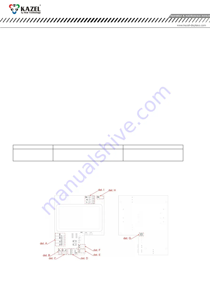
Controller
The controller is a device responsible for the process of displaying the content by the light signalling device.
5.1
Controller connectors
det. A, det. B, det. C
– LED module connectors;
det. D
– RS-485/RS-422 connector;
det. E
– 0/20mA digital current loop;
det. F
– RS-232
connector;
det. G
–
DEF
microbutton;
det. H
– housing earthing soldering point;
det. I
– network power supply connector
Fig. 7


