background image


DTR_314-01-01-001_EN_d


5.


MINI extender  

The extender module is a component of the display for weighing scales, which enables the communication with 
peripheral devices. 

5.1


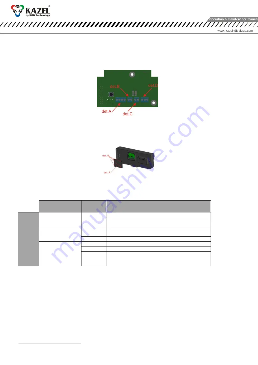
Extender Connectors  


det. A

 – LAN (optional); 

det. B

 – RS-232; 

det. C

 – 0/20mA digital current loop; 

det. D

 – RS-485/RS-422  

Fig. 5 

5.2


List of extender connectors in the WA-1 MINI display for weighing scales  

Table 2 presents an overview of the extender connectors in the WA-1 MINI display for weighing scales. These 
connectors are available after removing the cover (Fig. 6)  


det. A

 – extender cover, 

det. B

 – cover fixing screws 

Fig. 6 

NOTICE! 

The disassembly of the housing must be made with the disconnected power supply. When doing this, take special 
caution because of the possibility of electric shock  


Interface / Function 

Connector 

symbols  

Notes  

STA

N

D

RAD

5


RS-232 

RA 

RDX line of the RS-232 interface. The line should be connected 
with the weighing terminal output.  

RK 

GND line of the RS-232 interface  

0/20 mA (CL) digital 

current loop  

CA 

CL line of the current loop. The line should be connected with 
the weighing terminal TDX output 

CK 

GND line of the current loop interface  

RS-485  RS-422 

RS-485 and RS-422 interface non-inverting line 

RS-485 and RS-422 interface inverting line  

GND 

GND line of the RS-485 and RS-232 interface for use at risk of a 
significant difference in the potentials of the display mass and 
the weighing terminal mass  

Table 2 

5.2.1


RS-232 connector: 

For configuration purposes, the user connects with the display for weighing scales via the RS-232 connector (Fig. 5), 
using the computer with the RGB WagSet 2 software installed. 

5.2.2


RS-485 / RS-422 connector: 

For configuration purposes, the user connects with the display for weighing scales via the RS-485 or RS-422 connector 
(Fig. 5), using the computer with the RGB WagSet 2 software installed.  

5.2.3


0/20mA digital current loop: 

For communication purposes, the user connects with the display for weighing scales via the digital current loop 
connector (Fig. 5), using the computer with the RGB WagSet 2 software installed. 


5

 on the Extender PCB there are located all connectors available as standard (RS-232, RS-485, RS-422), 0/ 20mA (CL) digital current loop, 

however, only the RS-232 interface cable (without a tip) is led out.


Summary of Contents for KAZEL WA-1 MINI

Page 1: ...OPERATION AND MAINTENANCE MANUAL WA 1 MINI Product code 314 01 01 Explanatory figure ...

Page 2: ...otocols 5 4 3 1 1 Embedded user menu micro switch 5 4 3 1 2 Interface transmission parameters and communication speed 6 4 3 1 3 RGB WagSet 2 software 6 5 MINI extender 7 5 1 Extender Connectors 7 5 2 List of extender connectors in the WA 1 MINI display for weighing scales 7 5 2 1 RS 232 connector 7 5 2 2 RS 485 RS 422 connector 7 5 2 3 0 20mA digital current loop 7 6 Automatic brightness control o...

Page 3: ...ansportation Due to protective packaging the device should be stored in the temperature 25 C 60 C 13 F 140 F at the humidity below 99 RH 3 Device construction WA 1 MINI has a housing made of polycarbonate which is resistant to UV radiation and has a high mechanical strength By using the thermo moulded housing and a rear sealing layer the device when properly assembled meets the IP66 tightness requ...

Page 4: ...ion or improper use may cause the property damage loss of health or death from electrical shock In addition any failure to follow the manufacturer s instructions may void your warranty NOTICE Keep in mind that the device should be mounted with the wires facing down NOTICE It is forbidden to make any additional mounting points or any holes in the device assembly components and in the device itself ...

Page 5: ...d by the Autolearn function the default unit will be set Depending on the purchased regional version it is kg or lb The Autolearn mode supports the following transmission parameters Baud rate 2400 4800 9600 19200 Transmission parameters data bits parity stop bits 8N1 7E1 7O1 4 3 WA 1 MINI manual configuration The configuration of the device using RGB WagSet 2 enables among others 1 Precise definin...

Page 6: ...g down the microbutton until the message Saved appears while exiting the custm option happens automatically after 30 seconds of user inactivity 4 reset This option allows you to restore the default settings of the remote display and to activate the Autolearn mode In addition in the devices with the Ethernet interface you can restore the default network layer settings IP address 192 168 0 11 networ...

Page 7: ...e line should be connected with the weighing terminal TDX output CK GND line of the current loop interface RS 485 RS 422 A RS 485 and RS 422 interface non inverting line B RS 485 and RS 422 interface inverting line GND GND line of the RS 485 and RS 232 interface for use at risk of a significant difference in the potentials of the display mass and the weighing terminal mass Table 2 5 2 1 RS 232 con...

Page 8: ...end the configuration to the display for weighing scales If the user does not enter the configuration the display will start the Autolearn procedure If the process is successful the Ready text is shown and then the unit is ready to show weighting results 8 Disposal and recycling 8 1 Recycling of packing materials The packaging materials must be segregated then recycled in accordance with local reg...

Reviews: