User Manual
Reference number: 4111A-RADAR4600-GBD-R1.1
Date: 27 February 2018
Page 67 of 149
3.5.7
Parallel Index Lines - PI
To get easier evaluation of fixed and moving targets, Index lines can be called up into radar image. They are
also useful as lane control, when checking XTD without EPFS.
Up to 12 separate line sets can be activated, with up to 10 parallel lines in 4 different styles and each set can
be moved and adjusted independent from the others.
-
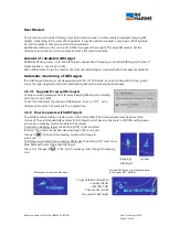
Click down right side menu button [PI LINES], to activate the menu ‘PI LINES’.
-
Click one of the arrow buttons in the upper line or click into ‘Line Set’, to select a line number (1 – 10).
-
Click the Style button and select one of shown styles.
-
Set the tick mark beside of ‘SHOW’.
Now the selected kind and number of lines are shown magenta coloured parallel to ships heading, with a
separation dash, which is positioned perpendicular to Own Ship. Beside of the dash, the selected line
number is set.
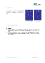
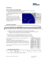
In following example line no. 1, consisting of two parallel lines (see ‘NUMBER OF LINES') is chosen. In this
case they are manually set to another bearing.
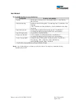
Following parameter can be altered
:
Port or STB side of OS: - Click the button, which shows the selected side [STBD] or [PORT]. To change, click
the alternative one. The index line jumps to other side of OS.
Relative or True Bearing: - To change, click the button [REL] respective [TRUE] and select the alternative.
Then the adjustable bearing value shows a value according to set mode. – The left of button [REL] respective
[TRUE] shown ‘T BRG xxx’ cell is not changeable. It indicates always True bearing.
Distance to Own Ship: - Click in menu ‘Bearing / Range’ the needed arrow buttons beside of the distance
value or click direct the distance value and change set distances to Own Ship from 0 to any wanted distance
in NM.
Bearing to Own Ship: - Click in menu ‘Bearing / Range’ the needed arrow buttons to set bearing related to
Own Ship from 0 to 359.9° The lines are turned around OS, so that the dividing dash always is directed
perpendicular to OS. An arrow beside of the dash line of the first line indicates the direction of bearing.
If Relative bearing is selected, the value in bearing menu is a relative bearing. Down beneath, the regarding
True value is shown. If True bearing is selected, both values are the same.
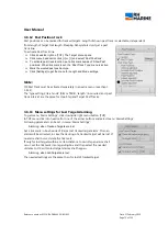
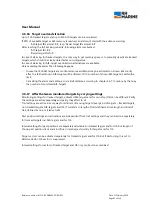
In shown example, also truncate lines are visible (No. 2). The regarding description follows on next page.


