background image

Sa

fe

ty

 In

fo

rm

at

io

n

SAFETY INFORMATION

!

WARNING

IN COMPLIANCE WITH RECOGNIZED CODES, IT IS REC-
OMMENDED THAT AN AUXILIARY DRAIN PAN BE IN-
STALLED UNDER THIS FURNACE AND ANY INSTALLED
EVAPORATOR COIL THAT IS LOCATED IN ANY AREA OF
A STRUCTURE WHERE DAMAGE TO THE BUILDING OR
BUILDING CONTENTS MAY OCCUR AS A RESULT OF AN
OVERFLOW OF THE A/C COIL DRAIN PAN.

!

WARNING

DO NOT INSTALL THIS FURNACE IN A MOBILE HOME!!
THIS FURNACE IS NOT APPROVED FOR INSTALLATION
IN A MOBILE HOME.  DOING SO COULD CAUSE FIRE,
PROPERTY DAMAGE, PERSONAL INJURY OR DEATH.

!

WARNING

INSTALL THIS FURNACE ONLY IN A LOCATION AND PO-
SITION AS SPECIFIED IN THE LOCATION REQUIRE-
MENTS AND CONSIDERATIONS SECTION OF THESE
INSTRUCTIONS.

!

WARNING

IMPROPER INSTALLATION CAN RESULT IN UNSATISFAC-
TORY OPERATION AND/OR DANGEROUS CONDITIONS
AND ARE NOT COVERED BY THE MANUFACTURER’S
WARRANTY.

!

WARNING

DO NOT BYPASS, JUMPER, OR REMOVE ANY SAFETY
SWITCH FROM THE FURNACE CONTROL CIRCUIT. IF A
SAFETY SWITCH CAUSES THE FURNACE TO SHUT
DOWN OR OPERATE INTERMITTENTLY, IT IS AN INDICA-
TION OF A POTENTIAL SAFETY HAZARD THAT MUST BE
ADDRESSED BY A QUALIFIED TECHNICIAN, SERVICE
AGENCY OR THE GAS SUPPLIER.  DO NOT RESET
SAFETY CONTROLS WITHOUT CORRECTIVE ACTION
AND/OR VERIFICATION OF PROPER SAFE OPERATION
BY A QUALIFIED INSTALLER, SERVICE AGENCY OR THE
GAS SUPPLIER.

REPLACE ANY SAFETY CONTROL COMPONENT ONLY
WITH IDENTICAL OEM REPLACEMENT PARTS.  WHEN A
NEW SAFETY SWITCH IS INSTALLED, IT MUST BE
TESTED FOR A MINIMUM OF 15 MINUTES WITH THE
FURNACE OPERATING AT MAXIMUM INPUT RATE AND
WITH BOTH BLOWER AND BURNER DOOR INSTALLED.
IF THE FURNACE IS INSTALLED IN A CLOSET, THE
CLOSET DOOR MUST ALSO BE CLOSED FOR THIS
TEST.  REPEAT THE TEST AT THE MINIMUM INPUT RATE
IF THE FURNACE IS A MULTI-STAGE FURNACE.

!

WARNING

USE ONLY WITH THE TYPE OF GAS APPROVED FOR
THIS FURNACE.  REFER TO THE FURNACE RATING
PLATE.

!

WARNING

NEVER TEST FOR GAS LEAKS WITH AN OPEN FLAME.
USE A COMMERCIALLY AVAILABLE SOAP SOLUTION
MADE SPECIFICALLY FOR THE DETECTION OF LEAKS
TO CHECK ALL CONNECTIONS, AS SPECIFIED IN GAS
SUPPLY AND PIPING SECTION OF THESE INSTRUC-
TIONS.

!

WARNING

COMBUSTION PRODUCTS MUST BE DISCHARGED OUT-
DOORS.  CONNECT THIS FURNACE TO AN APPROVED
VENT SYSTEM ONLY, AS SPECIFIED IN THE VENT PIPE
INSTALLATION SECTION OF THESE INSTRUCTIONS.

!

WARNING

WHEN A FURNACE IS INSTALLED SO THAT SUPPLY
DUCTS CARRY AIR CIRCULATED BY THE FURNACE TO
AREAS OUTSIDE THE SPACE CONTAINING THE FUR-
NACE, THE RETURN AIR SHALL ALSO BE HANDLED BY
DUCT(S) SEALED TO THE FURNACE CASING AND TERMI-
NATING OUTSIDE THE SPACE CONTAINING THE FUR-
NACE.

!

WARNING

WHENEVER THE FACTORY RETURN-AIR CONNECTION
IS NOT USED IT MUST BE SEALED. A SOLID METAL 
BASE PLATE MUST BE INSTALLED AND SEALED. FAC-
TORY BASE PLATES ARE AVAILABLE AS ACCESSORY
ITEMS. (PART NUMBERS ARE LISTED IN THE SPEC
SHEET FOR THE FURNACE.) FAILURE TO INSTALL AND
SEAL THE BASE PLATE AND RETURN AIR DUCT CON-
NECTIONS MAY ALLOW CARBON MONOXIDE AND
OTHER CONTAMINANTS TO BE DRAWN INTO THE CON-
DITIONED AIR SPACE AND DISTRIBUTED THROUGHOUT
THE HEATED SPACE.

!

WARNING

DO NOT OPERATE THE SYSTEM WITHOUT FILTERS. A
PORTION OF THE DUST ENTRAINED IN THE AIR MAY
TEMPORARILY LODGE IN THE AIR DUCT RUNS AND AT
THE SUPPLY REGISTERS. ANY CIRCULATED DUST PAR-
TICLES WILL BE HEATED AND CHARRED BY CONTACT
WITH THE FURNACE HEAT EXCHANGER. THIS SOOTY
RESIDUE WILL SOIL CEILINGS, WALLS, DRAPES, CAR-
PETS AND OTHER HOUSEHOLD ARTICLES. SOOT DAM-
AGE MAY ALSO RESULT WITH, OR WITHOUT, FILTERS IN
PLACE, WHEN CERTAIN TYPES OF CANDLES ARE
BURNED, OR CANDLEWICKS ARE LEFT UNTRIMMED.

6

!

WARNING

COMBUSTION AND VENTILATION AIR MUST BE PRO-
VIDED TO THE FURNACE AS REQUIRED BY THE NA-
TIONAL FUEL-GAS CODE (U.S.) AND CSA B149.1
(CANADA) AND THE COMBUSTION AND VENTILATION
AIR SECTION OF THESE INSTRUCTIONS.

Summary of Contents for (-)(-)80MSX050A30SA

Page 1: ...L SERIES 80MSX UPFLOW HORIZONTAL SERIES U L and or C S A recognized fuel gas and CO carbon monoxide detectors are rec ommended in all applications and their installation should be in accordance with the manufacturer s recommendations and or local laws rules regulations or customs Factory Use Only ST A1220 01 X0 92 24161 144 01 SUPERSEDES 92 24161 144 00 ...

Page 2: ...ccessories 30 Electronic Air Cleaner 30 Humidifier 30 Filter 30 RXGW B01 Chimney Adapter 30 Four Inch Flue Adapter 30 11 TWINNING 32 Furnace Twinning Installations 32 Control Boards 33 34 12 HIGH ALTITUDE 35 Natural Gas at High Altitudes 35 LP Gas at High Altitudes 37 13 STARTUP PROCEDURES 38 Sequence of Operation 38 14 DIAGNOSTICS AND FAULT CODES 39 15 LOCKOUT 40 16 FIELD SELECTIONS ADJUSTMENTS 4...

Page 3: ...orrect open the carton and verify that the furnace rating label specifies the same furnace model number that is speci fied on the carton label If the model numbers do not match re turn the furnace to the distributor IMPORTANT Proper application installation and maintenance of this furnace and system is a must if consumers are to receive the full benefits for which they have paid The 801T 80MSX ser...

Page 4: ...A90A Installation of Air Conditioning and Ventilating Sys tems NFPA90B Installation of warm air heating and air conditioning systems The equipment has been evaluated in accordance with the Code of Federal Regulations Chapter XX Part 3280 CALIFORNIA RESIDENTS ONLY IMPORTANT All manufacturer products meet current Federal OSHA Guidelines for safety California Proposition 65 warnings are required for ...

Page 5: ...perature rise in heat record air temperature rise ______ Air temperature rise in cool record air temperature rise VENTING ______ Correct vent pipe diameter and length according to NFGC tables _________________ Vent connection size ______ Correct venting material according to NFGC tables ______ Correct lining for masonry chimneys ______ Adequate clearance from combustibles ______ Proper negative pr...

Page 6: ...ONLY WITH THE TYPE OF GAS APPROVED FOR THIS FURNACE REFER TO THE FURNACE RATING PLATE WARNING NEVER TEST FOR GAS LEAKS WITH AN OPEN FLAME USE A COMMERCIALLY AVAILABLE SOAP SOLUTION MADE SPECIFICALLY FOR THE DETECTION OF LEAKS TO CHECK ALL CONNECTIONS AS SPECIFIED IN GAS SUPPLY AND PIPING SECTION OF THESE INSTRUC TIONS WARNING COMBUSTION PRODUCTS MUST BE DISCHARGED OUT DOORS CONNECT THIS FURNACE TO...

Page 7: ...EAS ALL JOINTS SEAMS AND OPENINGS IN THE EQUIPMENT AND DUCT MUST BE SEALED TO LIMIT THE MIGRATION OF TOXIC FUMES AND ODORS IN CLUDING CARBON MONOXIDE FROM MIGRATING INTO THE LIVING SPACE IF AIR MOVING EQUIPMENT OR DUCTWORK IS LO CATED IN SPACES CONTAINING FUEL BURNING AP PLIANCES SUCH AS WATER HEATERS OR BOILERS ALL JOINTS SEAMS AND OPENINGS IN THE EQUIP MENT AND DUCT MUST ALSO BE SEALED TO PRE VE...

Page 8: ...r the center of the pro posed or existing duct system 2 Give consideration to the vent system piping when se lecting the furnace location Be sure the venting system can get from the furnace to the termination with minimal length and elbows 3 Locate the furnace near the existing gas piping Or if running a new gas line locate the furnace to minimize the length and elbows in the gas piping See Figure...

Page 9: ...S PLACEMENT OF COMBUSTIBLE MATERIALS ON AGAINST OR AROUND THE FURNACE JACKET CAN CAUSE AN EXPLOSION OR FIRE RESULTING IN PROP ERTY DAMAGE PERSONAL INJURY OR DEATH THE HOMEOWNER SHOULD BE CAUTIONED THAT THE FUR NACE AREA MUST NOT BE USED AS A BROOM CLOSET OR FOR ANY OTHER STORAGE PURPOSES WARNING UPFLOW AND HORIZONTAL FURNACES ARE DESIGN CERTIFIED FOR INSTALLATION ON COMBUSTIBLE FLOORS NOTE HOWEVER...

Page 10: ...MAY REQUIRE 3 TO 4 OR 3 TO 5 ADAPTER 4 ADAPTER INCLUDED WITH 801P UNITS MAY BE 0 WITH TYPE B VENT MAY BE 1 WITH TYPE B VENT LEFT SIDE REDUCED CLEARANCE IN SHIP WGTS FIGURE 4 UPFLOW HORIZONTAL DIMENSIONS Location REDUCED CLEARANCE IN Model A B C D E F Left Right Back Top Front Vent Ship Side Side Wgts 50K 14 12 27 32 10 5 8 11 1 2 1 7 8 0 4 0 1 3 6 85 lbs 75K 17 1 2 16 11 32 12 3 8 15 2 1 2 0 3 0 1...

Page 11: ...e unit filter 7 NOTE Where the maximum airflow is 1800 CFM or more BOTH sides or the bottom must be used for the return air Do not take return air from the back of the unit NOTE DO NOT take return air from furnace rooms garages or cold areas Avoid return air from utility rooms kitchens laundry rooms and bathrooms DUCTING Ducting WARNING BLOWER AND BURNERS MUST NEVER BE OPERATED WITHOUT THE BLOWER ...

Page 12: ...E 2 SCREWS LIFT BASE UP SLIDE FORWARD TO REMOVE 2 INSTALLATION IS REVERSE OF REMOVAL VERIFY REAR FLANGE IS SEALED PROPERLY AS SHOWN IN DETAIL ST A1220 10 X0 SOLID BASE FLANGE FITS UNDER CABINET BOTTOM FIGURE 6 FIGURE 7 ST A1220 10 ST A1220 11 ST A1220 08 NOTE SOLID BASE PLATE PROVIDED WITH 801T MODELS ONLY WHEN SOLID BASE PLATE IS USED TAPE AROUND BOTTOM FLANGES OF CABINET BEFORE THE UNIT IS INSTA...

Page 13: ... from an adjacent fuel burning appliance NOTE Do not block furnace access with support rods Maintain clearances recommended in Figure 8 Allow enough space for proper service maintenance or re placement of the heat exchanger and blower assembly DUCTING FOUR ANGLE BRACKETS SHIPPED WITH 801T UNITS CAN BE IN STALLED HORIZONTALLY THESE BRACKETS MAY BE USED TO SE CURE THE RETURN AIR DUCT TO A HORIZONTAL...

Page 14: ...total input of all appliances in the space If the open space contain ing the appliances is in a building with tight construction contem porary construction outside air may still be required for the appliances to burn and vent properly Outside air openings should be sized the same as for a confined space IMPORTANT ONLY THE CURRENT VENT INSTRUCTIONS APPLY All gas furnaces cannot be common vented OVE...

Page 15: ... inch of free area for each 1 000 BTUH of total input in the space Table 2 shows some typical examples of openings required for com bustion air openings required for a confined space B USING OUTDOOR AIR FOR COMBUSTION IMPORTANT Do not take air from an attic space that is equipped with power ventilation The confined space must communicate with the outdoors in accordance with Methods 1 or 2 below Th...

Page 16: ... EACH OPENING WHEN TWO OPENINGS ARE USED WITH A FURNACE 1 LOCATED IN A CONFINED SPACE 2 USING OUTDOOR AIR FOR COMBUSTION 3 COMMUNICATING DIRECTLY TO THE 3 OUTSIDE THROUGH AN OPENING OR 3 THROUGH A VERTICAL DUCT 16 Combustion Air COMBUSTION AND VENTILATION AIR cont TABLE 10 MINIMUMFREE AREA REQUIRED FOR EACH OPENING WHEN TWO OPENINGS ARE USED WITH A FURNACE 1 LOCATED IN A CONFINED SPACE 2 USING OUT...

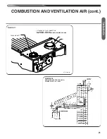
Page 17: ...IS IS NOT A REQUIREMENT SEE PREVIOUS PAGE SINGLE ELBOW IS ALLOWED BUT MAY NOT PREVENT DEBRIS FROM BEING DROPPED INTO THE FURNACE GROUND OR SHELF SURFACE 6 MIN 6 MINIMUM CLEARANCE PVC DOUBLE ELBOW 8 SCREWS METAL FLUE PIPE ONLY EXHAUST 8 SCREWS FIGURE 13 COMBUSTION AIR FITTING NON ATTIC COMBUSTION AIR PULL Combustion Air GAS WATER HEATER FURNACE OPTIONAL 1 SQ INCH PER 4000 BTUH INLET AIR GABLE VENT ...

Page 18: ...e attic must be ventilated by gable or soffit vents COMBUSTION AIR FROM ATTIC If attic combustion air is used the inlet air opening at the furnace must be protected from accidental blockage Install a 90 elbow pointing horizontally at the top of inlet air pipe See Figure 14 maximum of 2 45 or 90 elbows allowed NOTE Maximum length of pipe that may be used for combustion air is 10 feet with two elbow...

Page 19: ...chimneys Follow the National Fuel Gas Code ANSI Z223 1 or proper installation practices NOTE Follow combustion air instructions as outlined in this man ual Single wall vent connectors to B 1 vent or masonry chimneys may be used under the guidelines of the National Fuel Gas Code ANSI Z223 1 The entire length of the vent connector shall be readily ac cessible for inspection cleaning and replacement ...

Page 20: ... equipped appli ances shall not be greater than 75 percent of the vertical height of the vent Single appliance venting of a fan assisted furnace into a tile lined masonry chimney is prohibited The chimney must be lined with either Type B vent or with a listed single wall metal lining sys tem Reference National Fuel Gas Code ANSI Z223 1 See Fig ure 18 for typical B 1 vent chase NOTE A chimney adapt...

Page 21: ...IR cont FIGURE 17 FIGURE 18 DEDICATED VENTING THROUGH CHIMNEY WITH B 1 VENT FRESH AIR INLET ST A1220 09 01 1 STANDARD 3 FLUE CONNECTION 2 4 ADAPTER OPTIONAL SEE NATIONAL FUEL GAS CODE FOR SIZING OPTIONS 1 2 ST A1220 09 Combustion Air ...

Page 22: ...used openings in the com mon venting system NOTE Ensure existing venting system complies with latest addi tion of National Fuel Gas Code ANSI Z223 1 and all local codes regulations 1 Visually inspect the venting system for proper size and hori zontal pitch and determine that there is no blockage restric tion leakage corrosion or other deficiencies which could cause an unsafe condition 2 Insofar as...

Page 23: ...OR PROPANE GAS IS HEAVIER THAN AIR AND TENDS TO COLLECT AT LOWER LEVELS MAKING IT MORE DIFFICULT TO SMELL AT NOSE LEVEL NATURAL GAS IS LIGHTER THAN AIR AND WILL RISE POSSIBLY ACCUMULATING IN HIGHER PORTIONS OF THE STRUCTURE IF A GAS LEAK IS PRESENT OR SUSPECTED DO NOT ATTEMPT TO FIND THE CAUSEYOUR SELF NEVER USE AN OPEN FLAME TO TEST FOR GAS LEAKS THE GAS CAN IGNITE RESULTING IN DEATH PERSONAL INJ...

Page 24: ... 3 feet to easily remove the control valve assembly Install a manual shut off valve in the gas line outside the furnace cas ing The valve should be readily accessible to turn the gas supply on or off Install a drip leg in the gas supply line as close to the fur nace as possible Always use a pipe compound resistant to the action of liquefied petroleum gases on all threaded connections IMPORTANT Whe...

Page 25: ...ORIFICES MAY OR MAY NOT NEED TO BE CHANGED SEE THE SECTION TITLED HIGH ALTITUDE INSTALLATIONS OF THIS BOOK FOR INSTRUCTIONS FIGURE 20 TYPICAL GAS VALVE HONEYWELL REGULATOR CAP WARNING NEVER PURGE A GAS LINE INTO THE COMBUS TION CHAMBER NEVER USE MATCHES FLAME OR ANY IGNITION SOURCE FOR CHECKING LEAK AGE FAILURE TO ADHERE TO THIS WARNING CAN CAUSE A FIRE OR EXPLOSION RESULTING IN PROPERTY DAMAGE PE...

Page 26: ... any restrictions in the gas supply piping or enlarge the gas pipe See Tables 6 and 7 With LP gas have the LP supplier adjust the line pressure at the regulator MANIFOLD GAS PRESSURE MEASUREMENT Natural gas manifold pressure should be 3 5 w c LP gas manifold pressure should be 10 0 w c Only small variations in gas pressure should be made by adjusting the pressure regula tor 1 With the gas to the u...

Page 27: ... the gas supply to the furnace 2 Remove the burner door from the furnace 3 Remove the burner assembly handle with care 4 Remove the two screws attaching the NOx insert retainer bracket to the center panel and remove NOx inserts 5 Put the two screws back into the holes in the center panel 6 Re install the burner assembly 7 Replace burner door 8 Turn on electrical power and gas supply to the unit NO...

Page 28: ...ace must NOT be electrically connected to line volt age prior to reversing the electrical connection 2 Disconnect the wires from the door switch 3 Remove the junction box from the furnace cabinet wall by re moving the two screws that hold it to the cabinet Leave the wires connected to the junction box 4 Remove 7 8 plug from hole opposite j box location Drill 2 3 16 Ø holes in the jacket NOTE Dimpl...

Page 29: ...ot use 24 volt control wiring smaller than No 18 AWG Install the room thermostat in accordance with the instruction sheet packed in the box with the thermostat Run the thermostat lead wires inside the blower compartment and connect to low voltage terminals as shown on the wiring diagram Never install the thermostat on an outside wall or where it will be influenced by drafts concealed hot or cold w...

Page 30: ...ion of this manual for more information See National Fuel Gas Code for sizing options FILTERS See Figure 27 Keep filters clean at all times A filter is not provided with the furnace but one must be field supplied and installed It is recommended to replace the furnace filter periodically to maintain optimum furnace performance RXGW B01 CHIMNEY ADAPTER IMPORTANT CHIMNEY ADAPTER IS CERTIFIED FOR USE ...

Page 31: ...THE FURNCE AT THE LOCATIONS PROVIDED CUT OUT USING EMBOSSED ANGLES AS A GUIDE FOR PROPER SIZE 23 X 14 ST A1220 07 00 RXGF CB 6625 7 5 5 FIELD SUPPLIED FILTER ST A1220 06 X0 FIGURE 27 FILTER LOCATIONS ACCESSORIES FIELD INSTALLED OPTION ACCESSORIES cont HORIZONTAL RETURN ST A1220 06 00 RXGF CB ACCESSORY FILTER RACK FIELD SUPPLIED FILTER Accessories ...

Page 32: ...heating cooling or fan NOTE Duct system must be adequate to provide correct airflow to each furnace for supply and return UT ELECTRONIC CONTROLS 1194 250 CONTROL BOARD 62 104058 02 1 Single Stage Operation a Control board ONE is on furnace connected to the ther mostat b The 24 VAC supply to both control boards must be in phase with each other c Connect the C W and TWIN terminals to counterparts on...

Page 33: ...33 R Y G W COOLING CONTACTOR THERMOSTAT TWINNING CONTROL BOARDS FIGURE 28 UT ELECTRONIC CONTROLS 1194 250 CONTROL BOARD TWINNING CONNECTION SINGLE STAGE OPERATION ST A1220 25 00 Twinning ...

Page 34: ...34 R Y G W2 W1 COOLING CONTACTOR THERMOSTAT FIGURE 29 UT ELECTRONIC CONTROLS 1194 250 CONTROL BOARD TWINNING CONNECTION TWO STAGE OPERATION TWINNING CONTROL BOARDS cont ST A1220 26 00 Twinning ...

Page 35: ...eating Value I H Q 25000 1050 23 81ft3 I Sea Level input per burner 25000 H Sea Level Heating Value 1050 Q 23 81 ft3 Natural Gas per hour From Table F 1 of Natural Fuel Gas Code Handbook 2002 3 5 w c column Orifice required at Sea Level 43 From Table F 4 of National Fuel Gas Code Handbook 2002 Orifice required at 5000 ft elevation 4 de rate per thousand ft 45 Orifice required at 8000 ft elevation ...

Page 36: ...Y 90 FURNACE MODEL NATURAL GAS ORIFICE SELECTION BASED ON HEATING VALUE ELEVATION Table is derived from Appendix of the National Fuel Gas Code To determine the correct orifice for your installation consult the National Fuel Gas Code tables F 1 and F 4 2 Local utilities adjust the sea level heating value of gasses used at higher elevations to compensate for appliance operation at altitude Installer...

Page 37: ...de LP orifices are based on an 11 of water column pressure at the orifice which dif fers from products that use 10 of water column at the orifice This difference requires a deviation from the NFGC orifice size recom mendations The Sea Level input should still be reduced by 4 per thousand ft and the orifice size must be selected based on the reduced input in Table 9 Input per Orifice Altitude burne...

Page 38: ...ignition 4 The spark igniter is energized to light the gas burners and stays energized for the up to 7 seconds after the gas valve opens 5 8 seconds after the gas valve opens the remote flame sen sor must prove flame ignition for one second using the process of flame rectification If the burners don t light the system goes through another ignition sequence It does this up to four times before ente...

Page 39: ...as occurred four times in a row the control enters one hour lockout and fault codes 10 and 11 will be displayed alternately as described above 2 When flame is lost five times in a row the control enters one hour lockout and fault codes 10 and 13 will be displayed alternately as described above A D 3 While the control is in one hour lockout due to an unexpected flame the fault codes 14 unexpected f...

Page 40: ...hour period will commence after flame is no longer detected Dead Blower has been detected main limit circuit open for more than 150 seconds When voltage has unexpectedly been detected on the gas valve circuit and voltage goes away when inducer is shut off The seven segment display will alternately display 10 and the code number for the fault causing the lockout Lockout will auto matically be reset...

Page 41: ...etting of the SW1 dipswitch is OFF The factory setting display orientation is with the control placed in a vertical orientation and the low volt age terminal block T2 is in the bottom position Heat Blower Off Delay SW2 SW3 A means of controlling the HEAT speed blower off delay time is provided The dipswitches are labeled SW2 and SW3 The fol lowing table defines the settings SW2 SW3 OFF OFF 90 seco...

Page 42: ... cleared from the fault buffer after one week The fault buffer can also be manually cleared if this is de sired For the first 30 seconds after a change in state of dip switch SW4 the furnace control will wait to determine if the switch becomes on off on off on off or off on off on off on within 30 seconds When this action is detected within 30 sec onds the fault code memory buffer shall be cleared...

Page 43: ...ner orifices To change orifice spuds shut off the manual gas valve and re move the gas manifold On LP gas furnaces the LP gas supply pressure must be set between 11 and 13 w c by means of the tank or branch supply regulators The furnace manifold pressure should be set at 10 w c at the gas control valve For elevations up to 2 000 feet rating plate input ratings apply For high altitudes elevations o...

Page 44: ... local gas utility to obtain the yearly average heating value and orifice size required to fire each individual burner at 25 000 BTU HR NOTE Refer to the High Altitude Section of this manual and the National Fuel Gas Code for high altitude rate ad justment above 2 000 ft TABLE 11 METER TIME 0123 456 27829 2 A2B2 2B2C766 C 7028 C 76 D 2 02 C70E A28762 2C5F C2 27829 0 0 1 2 3 1 1 4 22 0 1 3 525 6787...

Page 45: ...air flow is too much or the manifold pres sure needs to be adjusted Use lower speed tap on the multi speed blower IMPORTANT The measured temperature rise should be in the middle of the range IMPORTANT Some high efficiency filters have a greater than nor mal resistance to airflow This can adversely affect furnace opera tion BE SURE TO CHECK AIRFLOW if using any filter other than factory provided fi...

Page 46: ...WARNING DISCONNECT THE ELECTRICAL SUPPLY TO THE FUR NACE BEFORE ATTEMPTING TO CHANGE THE BLOWER SPEED FAILURE TO DO SO CAN CAUSE ELECTRICAL SHOCK RESULTING IN SEVERE PERSONAL INJURY OR DEATH Low 894 775 655 595 533 496 462 423 357 Med Lo 971 912 875 839 804 758 713 684 644 Med 1117 1081 1051 1024 995 973 938 908 878 Med Hi 1326 1291 1275 1240 1204 1171 1144 1114 1077 High 1440 1432 1405 1382 1353 ...

Page 47: ...r correct the source of tripping If this unit is mounted in a closet the door must be closed when making this check PRESSURE SWITCH This furnace is equipped with a normally open pressure switch that monitors pressure conditions within the furnace vent system during the heating cycle There are several reasons for the pressure switch not to close 1 An inoperative induced draft blower 2 A loose or le...

Page 48: ...and through it to keep from overheating CAUTION DO NOT OPERATE THE SYSTEM FOR EXTENDED PE RIODS WITHOUT FILTERS A PORTION OF THE DUST ENTRAINED IN THE AIR MAY TEMPORARILY LODGE IN THE AIR DUCT RUNS AND AT THE SUPPLY REGIS TERS ANY RECIRCULATED DUST PARTICLES WILL BE HEATED AND CHARRED BY CONTACT WITH THE FURNACE HEAT EXCHANGER THIS RESIDUE WILL SOIL CEILINGS WALLS DRAPES CARPETS AND OTHER HOUSEHOL...

Page 49: ... replacement marking which can be obtained through the distributor if any are found to be illegible or missing REPLACEMENT PARTS Please visit www myrheem com myruud com for replace ment parts information DIAGNOSTICS Refer to Figure 33 for determining cause of unit problems WIRING DIAGRAM Figure 34 is a complete wiring diagram for the furnace A wiring diagram is also available on the unit SYSTEM OP...

Page 50: ...s or overtemperature limits do not need to be reset Make sure no flame rollout in burner compartment due to blocked flu or heat exchanger OVERFIRE ensure furnace is not overtemperature temp rise is above stated range Check gas valve proper orifice size gas pressure etc Is Limit circuit open or opening and closing Note IFC Status LED should be blinking a Fault Code Is the IFC sensing a good flame N...

Page 51: ...51 Wiring Diagram FIGURE 34 FOR MODELS WITH UT ELECTRONIC CONTROLS 1194 200 INTEGRATED FURNACE CONTROL AND DIRECT SPARK IGNITION ...

Page 52: ...52 CM 0814 ...

Reviews: