82
In
te
gr
at
ed
F
ur
na
ce
C
on
tro
l
contiguous (have continuity) across all devices and all
wire segments. This should be done by twisting the
shielding wires from adjacent segments together.
Further, the shielding for the entire system must be
grounded in a single location. Multiple grounds on the
shielding system are NOT permitted. The shield wire
should be connected to the C terminal, or ground, at
the indoor unit. The shield wire should NOT be
connected to any terminal at the Control Center (aka;
Thermostat). Connecting the shield to ground at both
ends can cause current loops in the shield, reducing
shield effectiveness.
4. When using existing wire from a previous installation,
be sure to trim the tip of the wire back past the
insulation and strip a small amount of insulation from
the wire to expose clean new copper for the
communicating connections. Fresh copper must be
exposed when making the communicating
connections or communications may not be properly
established.
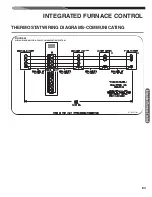
A. WIRING OF FULLY COMMUNICATING SYSTEMS.
Figure 56 is the wiring diagram for connecting the furnace
to an approved EcoNet communicating thermostat and
approved EcoNet communicating condenser. The only
approved configuration is to install dedicated wires directly
from the furnace to the thermostat and a separate set of
dedicated wires directly from the furnace to the condenser.
Additional EcoNet devices can be added to the system as
shown in Figure 56. The approved wiring configuration is
the daisy-chain configuration shown in Figure 56. A star
wiring configuration is not approved and should not be
used.
Note:
The only approved configuration requires that four
dedicated wires (E1,E2, R and C) be installed from the
furnace to the condenser.
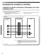
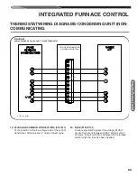
INTEGRATED FURNACE CONTROL
THERMOSTAT INPUTS
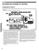
FIGURE 55
WIRING OF AUXILIARY INPUTS (USE WITH COMMUNICATING SYSTEMS ONLY).
ST-A1194-63 (TOP)

