48
90+ HIGH ALTITUDE
INSTRUCTIONS
90 PLUS CONDENSATING
GAS FURNACES HIGH
ALTITUDE KITS
These models can be converted for
high altitude using the appropriate
High Altitude Conversion Kits listed
below. The kits can be ordered from
the factory. The kit includes pressure
switch(es) and instructions for
converting the furnace for elevations
above 5,000 ft. The kit should never
be used at elevations below 5,000 ft.
In addition, the kit instructions detail
how to re-calculate burner orifice size
based on gas heating value and
elevation. The instructions are based
on a required 4% per thousand feet
reduction in input as specified by the
National Fuel Gas Code
(NFGC).
Specific orifices should always be
recalculated for all high altitude
installations as outlined below.
Orifices should be changed, if
necessary, based on gas heating
value and elevation.
90 PLUS CONDENSATING
GAS FURNACES HIGH
ALTITUDE OPTION
#278
Some furnaces are available from the
factory already converted for high
altitude elevations. The factory option
for high altitude elevations would be
ordered as a 278 option. These
factory converted furnaces come with
pressure switches for high-altitude
elevations already attached. Also,
different burner orifices are installed
at the factory which are one drill size
smaller (#51 DMS) than standard
90 Plus Condensing Gas Furnaces
(#50 DMS). The smaller orifice is
installed to accommodate for average
heating values expected in most high
altitude areas and a required 4% per
thousand feet reduction in input as
specified by the
National Fuel Gas
Code
(NFGC). Specific orifices
should always be recalculated for all
high altitude installations as outlined
below. Orifices should be changed, if
necessary, based on gas heating
value and elevation.
NATURAL GAS
INSTALLATION OF THIS FURNACE
AT ALTITUDES ABOVE 2000 FT (610
m) SHALL BE IN ACCORDANCE
WITH LOCAL CODES, OR IN THE
ABSENCE OF LOCAL CODES, THE
NATIONAL FUEL GAS CODE, ANSI
Z223.1/NFPA 54 OR NATIONAL
STANDARD OF CANADA, NATURAL
GAS AND PROPANE INSTALLATION
CODE, CAN B149.1.
INSTALLATION OF THIS APPLIANCE
AT OR ABOVE 5000 FT (1525 M)
SHALL BE MADE IN ACCORDANCE
WITH THE LISTED HIGH ALTITUDE
CONVERSION KIT AVAILABLE WITH
THIS FURNACE.
ELEVATIONS ABOVE 2000 FT
REQUIRE THAT THE FURNACE
INPUT RATING BE ADJUSTED AND
THAT THE SIZE OF THE BURNER
ORIFICES BE RE-CALCULATED
BASED ON ELEVATION AND GAS
HEATING VALUE. THE BURNER
ORIFICES MAY (OR MAY NOT) NEED
TO BE CHANGED. THE FOLLOWING
EXAMPLES SHOW HOW TO
DETERMINE IF AN ORIFICE CHANGE
WILL BE NECESSARY AND HOW TO
DETERMINE THE NEW ORIFICE SIZE.
IN CANADA, AS AN ALTERNATE TO
ADJUSTING THE BURNER ORIFICE
SIZE, THE MANIFOLD GAS
PRESSURE MAY BE ADJUSTED.
THIS METHOD IS COVERED LATER
IN THIS SECTION. THIS METHOD OF
ADJUSTING MANIFOLD PRESSURE
MAY ONLY BE USED IN CANADIAN
INSTALLATIONS.
34
⬙
90 Plus furnaces installed at high
elevations require the installation of a
high altitude kit for proper operation. The
high altitude kit consists of a high
altitude pressure switch that replaces
the pressure switch attached to the
induced draft blower. The kit also
contains gas orifices for high altitude.
The pressure switch must be installed at
elevations above 5000 ft. Elevations
above 2000 ft. require the furnace to be
de-rated 4% per thousand feet.
NOTE:
Factory installed orifices are
calculated and sized based on a sea
level Natural Gas heating value of
1075 BTU per cubic ft. Regional
reduced heating values may nullify
the need to change orifices except at
extreme altitudes.
The following are examples of orifice
sizing using the National Fuel Gas
Code Appendix F. For a simplified
estimation of orifice size based on
heating value and elevation, use
Tables 5 and 6. However,
calculations are the best method.
Example: 900 BTU/ft
3
Regional
Natural Gas Heating Value
I / H = Q
15000 / 900 = 16.68 ft.
3
I = Sea Level input (per burner):
15000
H = Sea Level Heating Value: 900
Q = 16.68 ft
3
Natural Gas per hour.
From Table F.1 of
National Fuel Gas
Code Handbook, 2002
(3.5
ⴖ
w.c.
column)
Orifice required at Sea Level: #48
From Table F.4 of
National Fuel Gas
Code Handbook, 2002
Orifice required at 5000 ft. elevation
(4% de-rate per thousand ft.): #50
Orifice required at 8000 ft. elevation
(4% de-rate per thousand ft.): #51
Example: 1050 BTU/ft
3
Regional
Natural Gas Heating Value
I / H = Q
15000 / 1050 = 14.63 ft.
3
I = Sea Level input (per burner):
15000
H = Sea Level Heating Value: 1050
Q = 14.28 ft.
3
Natural Gas per hour.
From Table F.1 of
National Fuel Gas
Code Handbook, 2002
(3.5
ⴖ
w.c.
column)
Orifice required at Sea Level: #50
From Table F.4 of
National Fuel Gas
Code Handbook, 2002
Orifice required at 5000 ft. elevation
(4% de-rate per thousand ft.): #51
Orifice required at 8000 ft. elevation
(4% de-rate per thousand ft.): #52
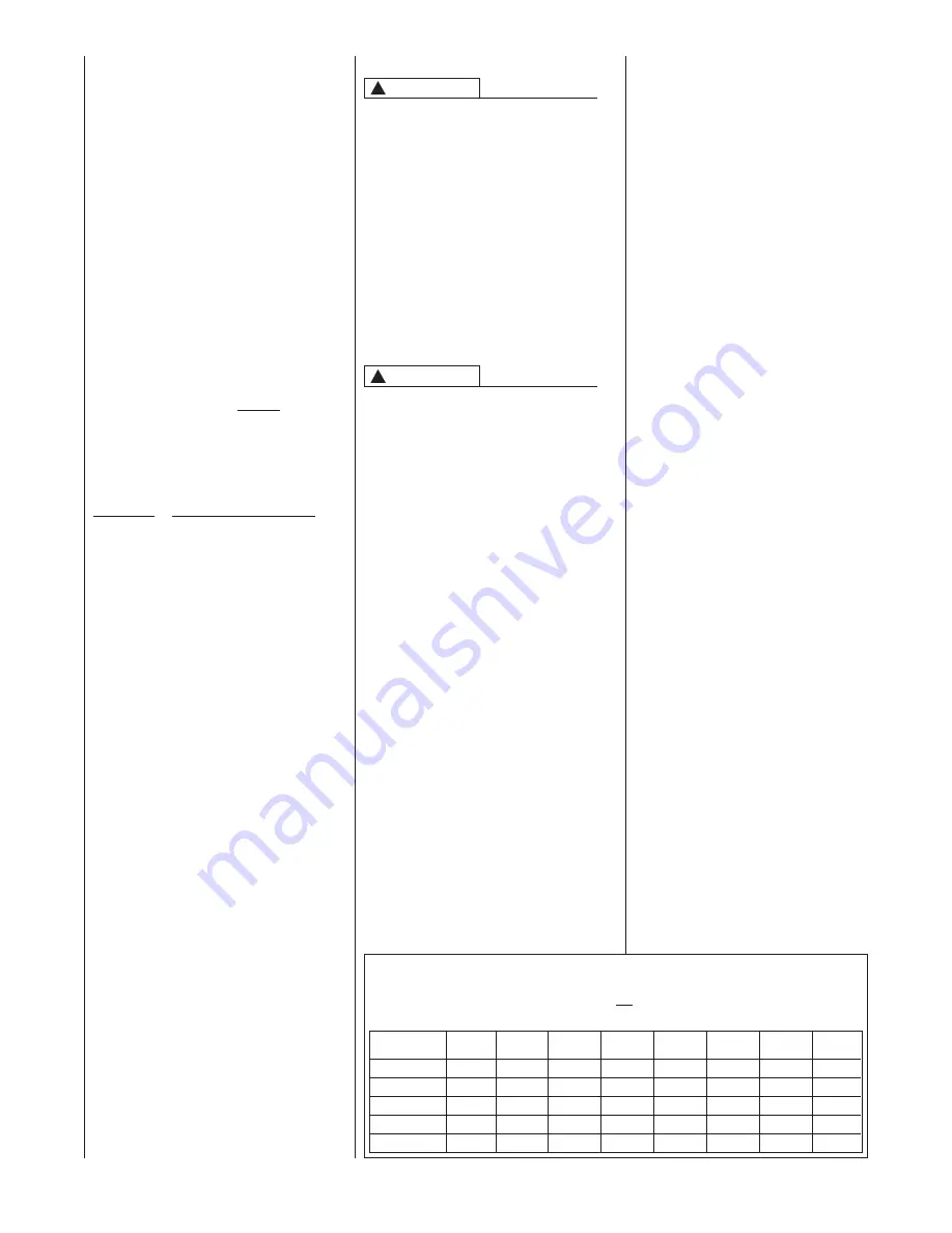
Natural Gas Orifice Drill Size (4% per 1000 ft. De-Rate)
IMPORTANT:
90 Plus Models only. Do not use this chart for any 80 Plus Models
Burner Input (per burner) 15,000 BTU @ Sea Level
Annual Avg. Heat
Value (btu per ft
3
)
850
900
1000
1075
1170
47
48
48
49
49
49
50
50
48
49
49
49
50
50
50
51
49
50
50
50
51
51
51
52
50
51
51
51
51
52
52
52
51
51
52
52
52
53
53
53
Sea level
to 1999 ft
2000 to
2999 ft
3000 to
3999 ft
4000 to
4999 ft
5000 to
5999 ft
6000 to
6999 ft
7000 to
7999 ft
8000 to
8999 ft
!
CAUTION
High
Altitude Kit BTU Input
RXGY-F04 105,000 BTU’s
RXGY-F05 120,000
RXGY-F06 45,000, 60,000 & 90,000
RXGY-F07 75,000
TABLE 5
!
CAUTION
Summary of Contents for GF901D Series
Page 60: ...60 FIGURE 52 MODELS WITH UT ELECTRONIC CONTROLS 1097 200 ...
Page 61: ...61 FIGURE 53 MODELS WITH UT ELECTRONIC CONTROLS 1097 200 ...
Page 62: ...62 ...
Page 63: ...63 ...
Page 64: ...64 CM 0611 ...


