background image

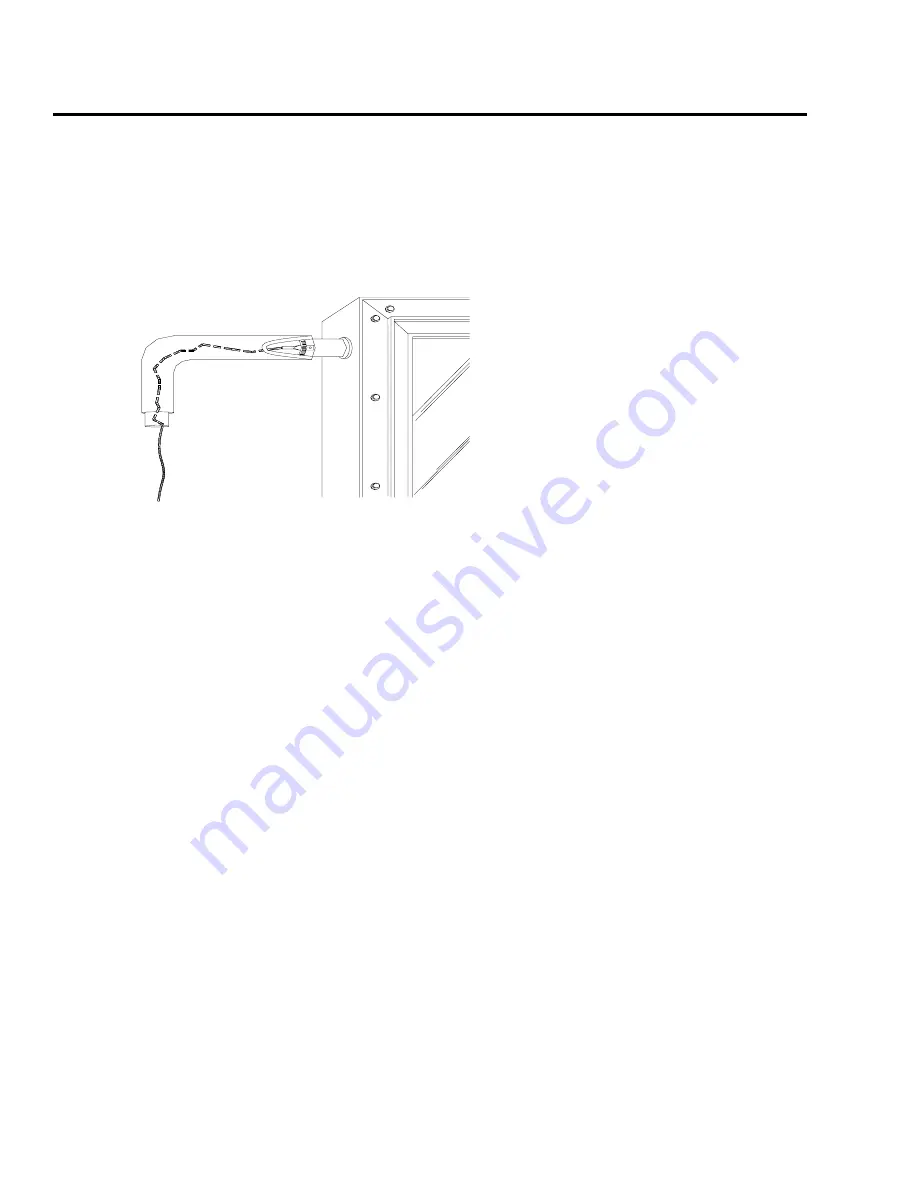
portion of the sensor to the collector header pipe 

with a stainless steel hose clamp. Wire nuts used 

to connect the sensor and low voltage wiring shall 

be all plastic, sealed with silicone and thoroughly 

wrapped in electrician’s tape.
The sensor "bundle" must be placed under the 

rubber pipe insulation covering the collector header. 

Thoroughly wrap and weatherize the insulation 

with electrician’s tape or insulation tape as provided 

by the manufacturer (Rubatex Insul-Tape or equal). 

See Figure 15 for collector sensor installation 

detail.

Low Voltage Wiring

The low voltage wiring used to connect the sensors 

to the controller should be a minimum18 AWG. 

The wiring should be bare or tinned copper, two 

conductor, PVC insulated, with a PVC UV rated 

gray jacket suitable for exterior use. Use Eastman 

Wire & Cable No. 5704, Belden Wire and Cable 

No. 8461 or equal.

 Installing the Solar Storage Tank 

and Expansion Tank

Refertotheinstallationmanualsforthestorage

tankandexpansiontank.
RefertoFigure16,SingleTankSystem

SchematicandFigures17,18,&19Double

TankSystemSchematiconpages28-31,forall

itemslistedas(No.##)throughoutthismanual.

In plumbing the solar storage tank and expansion 

tank make sure that all the components are 

accessible and easy to reach. Provide for clear 

access to the storage tank, pump, expansion tank, 

mixing valve, and other key components. If a 

component in the potable water side of the system 

may require future service or maintenance make 

the connections with brass unions. Use only brass 

nipples and unions and copper and brass fittings 

in plumbing the solar storage tank and expansion 

tank. The use of galvanized fittings or nipples, di-

electric unions, CPVC, PVC or other plastic pipe is 

prohibited.
Hard copper connections to the city cold water 

supply line and the home hot water feed lines 

are recommended. The gaskets in standard water 

heater flex hose connectors can become brittle and 

compressed over time and begin leaking on the 

water heater. If not detected in a timely manner 

even a small drip or leak may cause serious damage 

to the tank’s electrical components or, in extreme 

cases, may cause the tank to leak from the outside 

in.
Tank plumbing is required to provide for the 

isolation of the solar storage tank from the city 

cold water supply line by means of an isolating ball 

valve (No. 19).
Line thermometers shall be installed in the collector 

supply and return lines to allow for a simple 

diagnostic check of proper system operation. On 

a sunny day the hot water return line should be 

approximately 5 – 12° warmer than the water in 

the collector supply line. Compare the temperature 

readings in the two line thermometers (No. 22).
In a single tank system install a third thermometer 

(No. 22) directly after the mixing valve above the 

solar storage tank. In a two tank system you may 

install the third thermometer either directly above 

the hot outlet on the solar storage tank or after the 

mixing valve on the back-up water heater.

17

Figure 15

COLLECTOR  SENSOR


Summary of Contents for RESG75-40BP

Page 1: ...any terms within it seek professional advice Any questions regarding the operation maintenance service or warranty of this water heater should be directed to the seller from whom it was purchased If a...

Page 2: ...P RUSG75 40BP RUSG75 48BP RSG75 40BP RMSG75 40BP RMSG75 48BP RESG75 40BP RESG75 48BP SUSG75 40BP SUSG75 48BP SUSG75 48BC SUSG100 64BP PLEASE VISIT OUR WEB SITE FOR NEW PRODUCT UPDATES ANSWERS TO FREQU...

Page 3: ...all For Service section If you review our chart of Troubleshooting Tips first you may not need to call for service at all READ THIS MANUAL Your safety and the safety of others are very important There...

Page 4: ...Solar Energy Center in accordance with Section 377 705 Florida Statutes This certification does not imply endorsement or warranty of this product by the Florida Solar Energy Center or the state of Flo...

Page 5: ...us Burn 120 F 49 C More than 5 minutes 125 F 51 C 11 2 to 2 minutes 130 F 54 C About 30 seconds 135 F 57 C About 10 seconds 140 F 60 C Less than 5 seconds 145 F 63 C Less than 3 seconds 150 F 66 C Abo...

Page 6: ...ws rules regulations or customs LP gas must be used with great caution It is heavier than air and will collect first in lower areas making it hard to detect at nose level Before attempting to light th...

Page 7: ...tial water heaters of a capacity greater than 52 gallons consult the local building jurisdiction for acceptable bracing procedures Read and follow this Safety Information carefully SAVE THESE INSTRUCT...

Page 8: ...ctors in accordance with SRCC Standard OG 300 and all applicable national state and local codes ordinances and regulations governing solar water heating installations as well as good trade practices F...

Page 9: ...nheit if properly applied and maintained Use of uninhibited propylene glycol plain water or a concentration of these two fluids as the HTF in this system is strictly prohibited Propylene glycol can de...

Page 10: ...lation must be spaced far enough apart to prevent winter shading Table 1 shows the correct spacing between collectors to prevent shading on December 21 when the sun is at its lowest angle LATITUDE 25...

Page 11: ...r collector must be attached to the mounting hardware as detailed in Figures 5 10 Note The drawings in this manual detail mounting hardware for the series collector The collector must be raised from t...

Page 12: ...L BOLT W LOCKWASHER FLATWASHER ROOFING SEALANT 12 X 12 LEAD FLASHING 3 MIN CEDAR SHAKE OR SHINGLES ON ROOF FELT OVER ROOF DECK SHEATHING ON ROOF FRAMING SYSTEM BEAM OR RAFTER ST STL HANGER BOLT SET IN...

Page 13: ...NG NUT BLOCK BETWEEN RAFTERS FOR HANGAR BOLT ATTACHEMENT IF RAFTER SPACING DOES NOT MATCH BOTH SPACING SOLAR COLLECTOR MOUNTING GROOVE SIDE VIEW MOUNTING CLIP 3 8 ST STL BOLT W LOCKWASHER FLATWASHER R...

Page 14: ...14 Figure 9 Flush Mounting Installing the System Figures 5 10...

Page 15: ...15 Figure 10 Universal Tilt Mount Detail D...

Page 16: ...ee solder Notice Use of 50 50 lead solder is expressly prohibited Notice Use of galvanized steel CPVC PVC or any other type of plastic pipe is prohibited Piping in new solar installations can be cover...

Page 17: ...e water side of the system may require future service or maintenance make the connections with brass unions Use only brass nipples and unions and copper and brass fittings in plumbing the solar storag...

Page 18: ...ing upon the season and hot water demand The mixing valve described above blends the hot and cold water supplies to deliver hot water to your fixtures at a safe controlled temperature WARNING SCALDING...

Page 19: ...stem Close the lower isolation drain valve The collector loop now has been subjected to city pressure and the pressure gauge No 10 should read somewhere in the range of 50 75 PSI in most cases Make a...

Page 20: ...pressure exceeds this threshold Your solar water heating system must be charged and the fluid quality maintained by an experienced contractor If the system is drained during the winter or you notice...

Page 21: ...r water heating system When the glycol loop has been fully charged and the pressure is around 25 psi check the pressure gauge No 10 set the differential controller to the Automatic setting This will a...

Page 22: ...s throughout the day if desired 100 Utility Power Leave the thermostatic gas valve to your solar storage tank on and close the isolation ball valves in the collector loop Nos 6 and 8 In this mode of o...

Page 23: ...5 25 24 24 25 Figure 22a 100 Solar Operation Figure 22b Solar Preheat Operation Figure 22c 100 Utility Power Operation Figure 22d Valve Position Diagram Two Tank System Cold Inlet Hot Outlet See Handl...

Page 24: ...ght The collector radiates heat back to the atmosphere at night preventing the system from stagnating at very high temperatures This will not harm the pump or add substantially to your monthly utility...

Page 25: ...ush the tank on a semi annual basis Turn the thermostatic gas valve to the solar tank off before flushing Turn the controller to the off position Open the flush valve on the bottom of the storage tank...

Page 26: ...placement Used to charge the collector loop with glycol purge air from the loop and drain the heat exchange fluid Provided 8 Isolation Ball Valve Cash Acme 20800 204 or equivalent Used in conjunction...

Page 27: ...tank and to flush sediment from the tank on an annual basis Provided 19 Isolation Ball Valve Cold Water Supply Line When open allows potable water to fill the solar storage tank or back up water heat...

Page 28: ...n parallel Pipe Insulation Collector Return Cold Water Supply Inlet Hot Water Supply Outlet to Fixtures Feed 1 2 6 5 4 3 23 Optional Time Switch 7 8 9 10 11 12 13 14 15 16 18 17 19 20 21 22 22 22 Figu...

Page 29: ...urn Cold Water Supply Inlet Feed 1 2 4 23 Optional Time Switch Hot Water Supply Outlet to Fixtures 3 5 6 7 8 9 10 12 13 14 15 16 18 17 19 20 21 22 25 22 26 27 28 29 30 Roof Jacks Cold 11 24 Gas or Ele...

Page 30: ...tion Collector Return Cold Water Supply Inlet Feed 1 2 4 23 Optional Time Switch Hot Water Supply Outlet to Fixtures 9 12 13 14 15 16 17 19 21 22 24 22 26 27 30 Roof Jacks Heat Pump Back up Tank 25 20...

Page 31: ...Insulation Collector Return Cold Water Supply Inlet Feed 1 2 4 Hot Water Supply Outlet to Fixtures 9 12 13 14 15 16 17 19 21 22 24 22 26 27 Roof Jacks Tankless Back up 25 20 10 11 7 5 6 18 3 26 DOUBL...

Page 32: ...act the Manufacturer s National Service Department at the following address 1241 Carwood Court Montgomery Alabama 36117 Phone 1 800 432 8373 When contacting the manufacturer the following information...

Reviews: