123
nect the thermostat and condenser to
the furnace control.
For single stage condensers, a jumper
must be installed between Y1 & Y2 at
the furnace control.
NOTE:
A heat pump condenser cannot
be installed with this configuration.
There is no control for the reversing
valve.
STARTUP FOR SYSTEMS CONFIG-
URED WITH COMMUNICATIONS
INSTALLATION OF LINE VOLTAGE
AND GAS MUST BE PERFORMED
ACCORDING TO INSTRUCTIONS
WRITTEN IN THIS MANUAL. FAIL-
URE TO DO SO COULD RESULT IN
INJURY OR DEATH.
When the furnace is configured for
communications, the components on
the network (i.e. furnace, thermostat
and condenser) must establish commu-
nications before engaging a heat (or
other) thermostat demand. The proce-
dure for establishing communications is
automatic and is described below.
Once communications is established,
the start-up procedure will be the same
as the general start-up instructions
described in the section of this manual
titled
START-UP PROCEDURES
.
SPECIAL CONFIGURATION
– COMMUNICATING THER-
MOSTAT AND FURNACE
WITH A NON-COMMUNI-
CATING CONDENSER
Y1 and Y2 – These terminals may be
used to connect directly to a non-com-
municating condenser when a commu-
nicating thermostat is installed to the
furnace but a non-communicating con-
denser is installed in the system. While
the optimum configuration is with a
communicating condenser connected to
the network, there may be installations
where this is not desired. In these
cases, the thermostat will be communi-
cating with the furnace control and the
furnace control will energize the con-
denser as necessary (the additional
relays have been added to the furnace
control to allow this operation).
The thermostat connections labeled
“Y1” and “Y2” on the I.F.C. are normally
inputs
to the furnace control to turn on
the blower when they are energized.
However, in this configuration, these
(normally) inputs become
outputs
to
ene
rgize th
e condenser when a cooling
call has been sent from the communi-
cating thermostat.
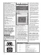
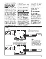
When this configuration is desired, use
the wiring diagram in Figure 97 to con-
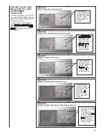
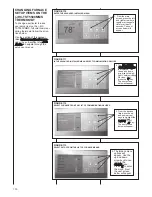
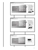
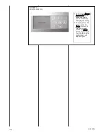
Once the communicating wiring is
properly installed and the furnace is
connected to line voltage, the sys-
tem can be turned on. The thermo-
stat will display the following text:
SEARCHING
is displayed several times for sever-
al seconds. N
ext, the text
FURNACE FOUND
and
AIR CONDITIONER FOUND
or
HEAT PUMP FOUND
(depending on which is installed in
the system) will be displayed. The
process can take several minutes
(up to a maximum of 30) to com-
plete. If these messages are not
displayed within 30 minutes after
energizing the system, communica-
tions can not be established. There
are many reasons why communica-
tions may not be established –
including improper settings of the
“TERM” and “BIAS” switches (see
BIAS / TERMINATION) and improp-
er wiring (see
WIRING A FURNACE
FOR COMMUNICATIONS
above).
FIGURE 97
WIRING DIAGRAM – SPECIAL CONFIGURATION: COMMUNICATING THERMOSTAT AND FURNACE WITH NON-COMMUNICATING CONDENSER
!
WARNING
ST-A1115-01 REV. 02
NOTE:
DEHUMIDIFICATION FUNCTION FROM A
COMMUNICATING THERMOSTAT WILL NOT
BE POSSIBLE WITH THIS CONFIGURATION.
Summary of Contents for RGFE
Page 92: ...92 TABLE 21 FURNACE FAULT CODES EXPANDED W DESCRIPTIONS AND SOLUTIONS CONTINUED ...
Page 93: ...93 TABLE 21 FURNACE FAULT CODES EXPANDED W DESCRIPTIONS AND SOLUTIONS CONTINUED ...
Page 94: ...94 TABLE 21 FURNACE FAULT CODES EXPANDED W DESCRIPTIONS AND SOLUTIONS CONTINUED ...
Page 95: ...95 TABLE 21 FURNACE FAULT CODES EXPANDED W DESCRIPTIONS AND SOLUTIONS CONTINUED ...
Page 96: ...96 TABLE 21 FURNACE FAULT CODES EXPANDED W DESCRIPTIONS AND SOLUTIONS CONTINUED ...
Page 97: ...97 TABLE 21 FURNACE FAULT CODES EXPANDED W DESCRIPTIONS AND SOLUTIONS CONTINUED ...
Page 98: ...98 TABLE 21 FURNACE FAULT CODES EXPANDED W DESCRIPTIONS AND SOLUTIONS CONTINUED ...
Page 99: ...99 TABLE 21 FURNACE FAULT CODES EXPANDED W DESCRIPTIONS AND SOLUTIONS CONTINUED ...
Page 102: ...102 TABLE 21 FURNACE FAULT CODES EXPANDED W DESCRIPTIONS AND SOLUTIONS CONTINUED ...
Page 103: ...103 TABLE 21 FURNACE FAULT CODES EXPANDED W DESCRIPTIONS AND SOLUTIONS CONTINUED ...
Page 104: ...104 TABLE 21 FURNACE FAULT CODES EXPANDED W DESCRIPTIONS AND SOLUTIONS CONTINUED ...
Page 105: ...105 TABLE 21 FURNACE FAULT CODES EXPANDED W DESCRIPTIONS AND SOLUTIONS CONTINUED ...

