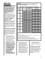
“rub-a-tex” insulation may also be
used as long as there is no heat
tape applied to the vent pipe. For
horizontal runs where water may
collect, wrap the vent pipe with
self-regulating 3 or 5 watt heat
tape. The heat tape must be
U.L. listed and installed per the
manufacturer’s instructions.
6. The minimum vent pipe length is
5 feet.
STANDARD INSTALLATIONS
The single-pipe system requires an
exhaust pipe only. Combustion air
may be taken from the furnace
installation area or ducted to the
furnace area from the outside.
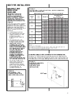
Size the exhaust pipe as specified in
Table 1. This table lists the maximum
allowable length in feet of the exhaust
pipe that may be used for all furnace
inputs as related to the number of
elbows required and the termination.
(See shaded area.)
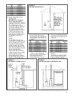
Vertical through-the-roof installations
do not require a vent termination. Use
2-in. PVC pipe extending a minimum
of 12 inches above the anticipated
level of snow accumulation. See
exhaust pipe requirements, Figure 20.
When 3-in. vent pipe is used from
furnace to the roof, reduce it to
2 inches before penetrating the roof.
A maximum of 18 inches of 2-in. pipe
may be used below the roof.
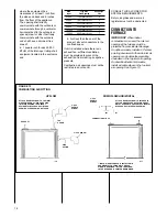
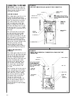
Horizontal vent terminations require a
2-in. PVC tee positioned 12 inches
from the outside wall. See exhaust
pipe requirements, Figure 21. When
3-in. pipe is used from the furnace to
the outside wall, reduce it to 2 inches
before penetrating the wall. A
maximum of 18 inches of 2-in. pipe
may be used inside the wall.
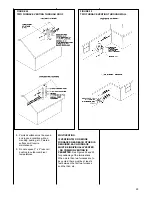
An alternate termination may be used
as shown in Figure 15 to clear
anticipated snow levels. The tee may
be raised up to 24 inches above the
wall penetration. Use two medium-
radius bend, 2-in. PVC elbows and a
length of 2-in. PVC pipe so that the
elbows are on 24-in. centers.
NON-DIRECT VENT TERMINATION
LOCATION REQUIREMENTS
MOISTURE IN THE COMBUSTION
PRODUCTS CONDENSES AS IT
LEAVES THE TERMINATION. THIS
CONDENSATE CAN FREEZE ON
EXTERIOR WALLS, UNDER THE
EAVES, AND ON SURROUNDING
OBJECTS. SOME DISCOLORA-
TION IS TO BE EXPECTED.
HOWEVER, IMPROPER LOCATION
18
OR INSTALLATION CAN CAUSE
STRUCTURAL OR EXTERIOR
FINISH DAMAGE TO THE
BUILDING.
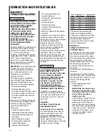
Non-direct venting location
requirements are slightly different in
some cases than direct venting. Install
a non-direct vent with the following
minimum clearances.
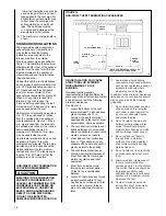
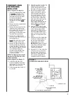
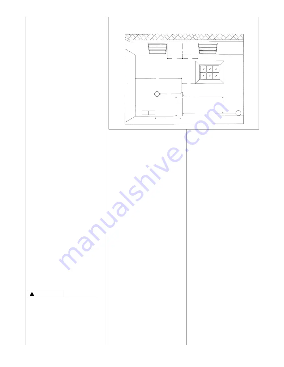
See Figure 16.
1. Locate the bottom of the vent
terminal at least 12 inches above
grade. Increase the 12-in.
minimum to keep the terminal
openings above the level of snow
accumulation, where applicable.
2. The vent shall not terminate over
public walkways or over an area
where condensate or vapor could
create a nuisance or hazard.
3. 4 feet below, 4 feet horizontally
from, or 1 foot above any door,
window soffit, under eave vent or
gravity air inlet to the building.
4. The vent terminal shall have a
minimum horizontal clearance of
4 feet from electric meters, gas
meters, regulators and relief
equipment.
5. 6 feet from an inside corner
formed by two exterior walls –
10 feet is the recommended
distance.
6. Locate it 3 feet above any forced
air inlet located within 10 feet.
Any fresh air or make-up air inlet,
such as for a dryer or furnace
area, is considered a forced air
inlet.
!
CAUTION
FIGURE 16
NON-DIRECT VENT TERMINATION CLEARANCES
I133
SOFFIT
VENTS
FRESH
AIR
INTAKE
*
NOTE: FOR DISTANCES OVER 10
*
NO
VERTICAL RESTRICTIONS APPLY.
INSIDE
CORNER
ELECTRIC
METER
10
*
RECOMMENDED
12
(
MIN.
UP TO10
*
*
4
*
4
*
3
*
4
*
4
*
4
*
6
*
7. Avoid areas where dripping
condensate may cause problems,
such as above planters, patios, or
adjacent to windows where
steam may cause fogging.
In addition to the minimum clearances
listed above, the vent location should
also be governed by the following
guidelines.
1. Do not terminate under any kind
of patio or deck. If running the
vent under a deck, insulate it to
insure no condensate freezes
and blocks the pipe.
2. Do not locate on the side of a
building with prevailing winter
winds. This will help prevent
moisture from freezing on walls
and overhangs (under eaves).
3. Do not extend vent directly
through brick or masonry
surfaces. Use a rust-resistant
sheet metal or plastic backing
plate behind vent.
4. Do not locate too close to shrubs
as condensate may stunt or kill
them.
5. Minimum vertical clearances of 1
foot are recommended for
overhangs up to 1 foot horizontal.
The vertical clearance should be
increased equally for each
additional increase in horizontal
overhang to a maximum vertical
clearance of 6 feet.
6. Caulk all cracks, seams and
joints within 6 feet horizontally
and above and below vent.
Summary of Contents for RGRA SERIES
Page 62: ...62...
Page 63: ...63...
Page 64: ...64 Rheem Manufacturing Company Air Conditioning Division Fort Smith Arkansas CM 1197...

