18
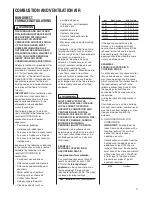
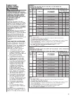
Input
Each Opening
45,000
100 square inches
60,000
100 square inches
75,000
100 square inches
90,000
100 square inches
105,000
105 square inches
120,000
120 square inches
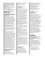
B. USING OUTDOOR AIR FOR
COMBUSTION
IMPORTANT:
Do not take air from
an attic space that is equipped
with power ventilation.
The confined space must
communicate with the outdoors in
accordance with Methods 1 or 2.
The minimum dimension of air
openings shall not be less than 3
inches. Where ducts are used,
they shall be of the same cross-
sectional area as the free area of
the openings to which they
connect.
Method 1
Two permanent openings, one
located within 12 inches of the top
and one located within 12 inches
of the bottom of the enclosure,
shall be provided. The openings
shall communicate directly, or by
ducts, with the outdoors or spaces
(crawl or attic) that freely
communicate with the outdoors.
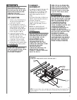
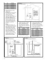
a. Where directly communicating
with the outdoors or where
communicating to the outdoors
through vertical ducts as shown in
Figure 11, each opening shall
have a minimum free area of 1
square inch for each 4,000 BTUH
of total appliance input rating in the
enclosure.
BTUH
Free Area
Round Pipe
Input
Each Opening
Size
45,000
11.25 square inches
4"
60,000
15.00 square inches
5"
75,000
18.75 square inches
5"
90,000
22.50 square inches
6"
105,000
26.25 square inches
6"
120,000
30.00 square inches
6"
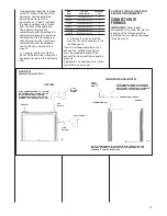
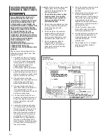
b. Where communicating with
outdoors through horizontal ducts,
each opening shall have a
minimum free area of 1 square
inch for each 2,000 BTUH of total
input rating of all equipment in the
enclosure (see Figure 12).
Here are some typical sizes:
BTUH
Free Area
Round Pipe
Input
Each Opening
Size
45,000
22.50 square inches
6"
60,000
30.00 square inches
6"
75,000
37.50 square inches
7"
90,000
45.00 square inches
8"
105,000
52.50 square inches
8"
120,000
60.00 square inches
9"
Method 2 (not shown)
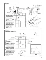
FIGURE 11
AIR FROM ATTIC/CRAWL SPACE
FIGURE 12
OUTSIDE AIR USING A HORIZONTAL DUCT
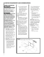
FIGURE 10
AIR FROM HEATED SPACE
NOTE:
EACH OPENING SHALL
HAVE A FREE AREA OF
NOT LESS THAN ONE
SQUARE INCH PER 1,000
BTU PER H0UR OF THE
TOTAL INPUT RATING OF
ALL EQUIPMENT IN THE
ENCLOSURE, BUT NOT
LESS THAN 100 SQUARE
INCHES.
GAS
WATER
HEATER
FURNACE
GAS
WATER
HEATER
GAS
WATER
HEATER
FURNACE
FURNACE
12" MAX.
12"
MAX.
1 SQ. INCH PER
4000 BTUH INLET AIR
OUTLET AIR 1 SQ. INCH
PER 2000 BTUH
INLET AIR 1 SQ. INCH
PER 2000 BTUH
1 SQ. INCH PER
4000 BTUH
OUTLET AIR
O
PT
IO
NA
L
1
SQ
.I
NC
H
PE
R
40
00
BT
UH
IN
LE
T
AI
R
VENTILATED
ATTIC GABLE OR
SOFFIT VENTS
GABLE
VENT
OUTLET AIR
IN ATTIC
MUST BE
ABOVE
INSULATION
Summary of Contents for RGRK SERIES
Page 41: ...41 FIGURE 39 TYPICAL MANIFOLD PRESSURE READING...
Page 45: ...45 FIGURE 43 UT Electronic Controls 1095 201 IFC TWINNING CONNECTION SINGLE STAGE OPERATION...
Page 60: ...60 FIGURE 53 TROUBLESHOOTING CHART or IFC not properly grounded Go To Next Page...
Page 61: ...61 FIGURE 53 TROUBLESHOOTING CHART CONTINUED...
Page 62: ...62 FIGURE 54 WIRING DIAGRAM...
Page 63: ...63...
Page 64: ...64 CM 0510...

