17
3.2.5 INSTALLATION IN CORROSIVE ENVIRONMENTS
The metal parts of this unit may be subject to rust or deterioration if exposed to a corro-
sive environment which can shorten its life. In addition to exposure to the exterior of the
cabinet, chemical contaminants inside the building that can be drawn into the unit from
the return air grille and attack structural metal parts, electrical components and the
indoor coil, causing premature failure of the unit. If the unit is to be installed in an area
where contaminants are likely to be a problem, special attention should be given to iso-
late the unit and return grille from contaminants.
3.3 AUXILIARY OVERFLOW PAN
In compliance with recognized codes, an auxiliary overflow pan must installed under all
equipment containing evaporator coils that are located in any area of a structure where
damage to the building or building contents may occur as a result of an overflow of the
coil drain pan or a stoppage in the primary condensate drain piping. See Section 6.3 of
this manual for information regarding the recommended auxiliary horizontal overflow pan
(model RXBM) for this air-handle.
3.4 CLEARANCES
• All units are designed for “0” inches clearance to combustible material on all cabinet
surfaces except for downflow application with higher kW electric heat as noted below.
• Some units require a combustible floor base depending on the heating kW if installed
in the downflow configuration on a combustible surface. The following table should be
used to determine these requirements.
• Units with electric heating kW equal to or less than the values listed in the table do not
require a combustible floor base. See Section 6.5 for Combustible Floor Base RXHB-XX.
• Units with electric heat require a one inch clearance to combustible material for the
first three feet of supply plenum and ductwork.
• Vertical downflow applications require clearance on at least one side of the unit for
electrical connections. Refrigerant and condensate drain connections are made on
the front of the unit.
• All units require 24 inches minimum access to the front of the unit for service.
• These units may be installed in either ventilated or nonventilated spaces.
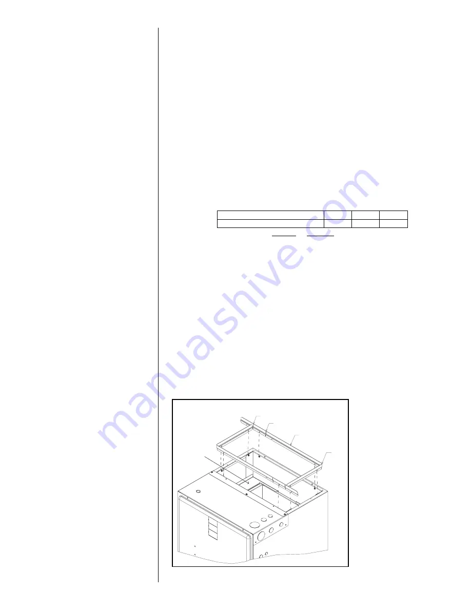
3.5 DUCT FLANGES
Duct flanges (4 pieces) are shipped with the unit and are to be field installed on the top
of the air-handler using the following procedure and referring to Figure 9.
1. Loosen the screws attaching the heat barrier to the cabinet.
2. Form a 90° bend with the short leg length at approximately 9.9” from the end where
the slot is cut in the flange to facilitate bending. The duct flanges are shipped sized for
the 24.5” wide cabinet. For the 17.5” and 21” wide cabinets, cut the long leg as
shown in Figure 9 to match the cabinet width.
3. Side the duct flanges onto the screws loosened in step one above. Tighten the
screws to secure the flanges.
Model Cabinet Size 17 21 24
Maximum Model Designation kW 15 18 20
21” CABINET CUT HERE
HEAT BARRIER
17” CABINET CUT HERE
DUCT FLANGE
(2) REQUIRED
BEND
FIGURE 9
DUCT FLANGE INSTALLATION


