11
- Tighten lug as tight as possible while holding circuit breaker. Check wires and make sure
each wire is secure and none are loose. Repeat for left wire bundle in left top circuit
breaker lug.
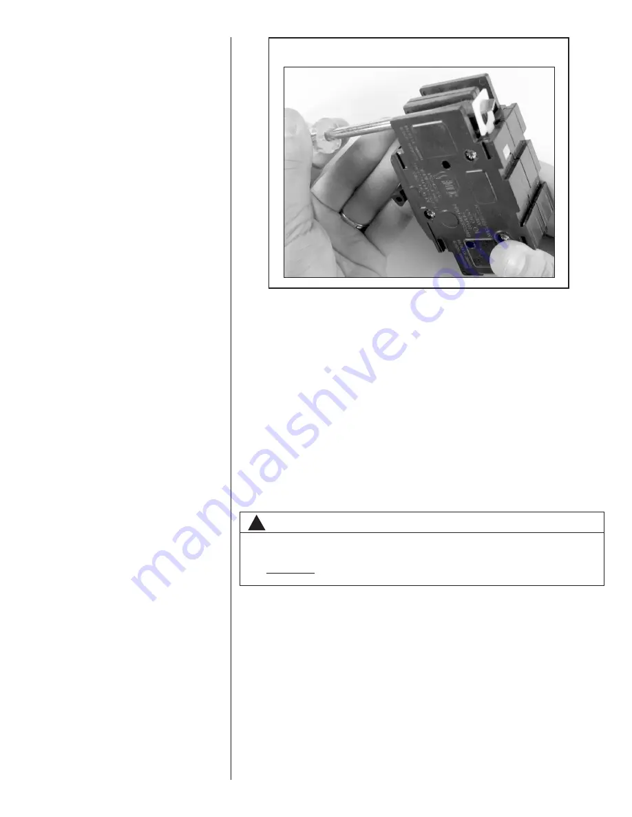
- Replace breaker by inserting breaker mounting tab opposite white pull tab in opening,
hook mounting tab over edge in opening.
- With screwdriver or pencil, pull white tab with hole away from breaker while setting that
side of breaker into opening. When breaker is in place, release tab, locking circuit break-
er into location in opening.
- Repeat above operation for remaining breaker(s) (if more than one is provided).
- Replace single point wiring jumper bar, if it is used, on line side of breaker and tighten
securely.
- Double check wires and lugs to make sure all are secure and tight. Check to make sure
unit wiring to circuit breaker load lugs match that shown on the unit wiring diagram.
DRIP LOOP: When installing the unit in down-flow or horizontal-right positions, make sure
that the wires coming from the motor form a proper drip loop. This allows water to cascade
off the lowest point of the wiring before it enters the motor head. This may require cutting
the wire tie and installing a new wire tie to form this loop.
• Rotate unit into the downflow position, with the coil compartment on top and the blower com-
partment on bottom.
• The set of coil rails must be moved for vertical down-flow and horizontal right applica-
tion. Remove the coil rail from the factory configuration (6 screws in all). Fastener clear-
ance holes will need to be drilled in the cabinet sides (proper hole locations are marked
with “dimples” for this purpose). Note that the shorter (no notch) coil rail must be mount-
ed on the left-hand side to provide clearance for the drain pan condensate connection
boss.
• Reinstall the indoor coil 180° from original position. Ensure the retaining channel is fully
engaged with the coil rail. (See Figure 5, Detail A.)
• Secondary drain pan kits RXBM- are required when the unit is configured for the hori-
zontal right position over a finished ceiling and/or living space. (See Section 16.0:
Accessories - Kits - Parts.)
IMPORTANT:
Units cannot be installed horizontally laying on or suspended from the
back of the unit.
!
WARNING
The RXHB-17, RXHB-21, or RXHB-24 combustible floor base is required when
certain units are applied downflow on combustible flooring. Failure to use the
base can cause a fire resulting in property damage, personal injury or death.
See clearances for units requiring a combustible floor base. See the accessory
section in this manual for combustible floor base RXHB-.
FIGURE 6
ROTATING CIRCUIT BREAKER
Summary of Contents for RH1V2417STANJA
Page 54: ...54 FIGURE 44 COMFORT CONTROL2 SYSTEM AIR HANDLER WIRING DIAGRAM H2V...
Page 55: ...55...
Page 56: ...56 CM 0115...


