22
NOTES:
•
Supply circuit protective devices may be fuses or “HACR” type circuit breakers.
•
Largest motor load is included in single circuit and multiple circuit 1.
•
If non-standard fuse size is specified, use next size larger fuse size.
•
J Voltage (230V) signal phase air handler is designed to be used with single or three phase 230 volt electric heaters. In the case of connecting
3-phase power to the air handler terminal block without the heater, bring only two leads to the terminal block. Cap, insulate and fully secure the
third lead.
•
?Heater Kit Connection Type A=Breaker B=Terminal Block C=Pullout Disconnect
RXBH-1724?05J
Single
208/240
1/60
3.6/4.8
17.3/20.0
1.7
25/30
24/28
2421HT
RXBH-1724?07J
Single
208/240
1/60
5.4/7.2
26.0/30.0
1.7
35/40
35/40
RXBH-1724?10J
Single
208/240
1/60
7.2/9.6
34.6/40.0
1.7
50/60
46/53
RXBH-1724?05J
Single
208/240
1/60
3.6/4.8
17.3/20.0
4.9
30/35
28/32
RXBH-1724?07J
Single
208/240
1/60
5.4/7.2
26.0/30.0
4.9
40/45
39/44
RXBH-1724?10J
Single
208/240
1/60
7.2/9.6
34.6/40.0
4.9
50/60
50/57
Single
208/240
1/60
10.8/14.4
51.9/60.0
4.9
80/90
72/82
3624HT
RXBH-1724A15J
MULTI. CKT 1
208/240
1/60
3.6/4.8
17.3/20.0
4.9
30/35
28/32
MULTI. CKT 2
208/240
1/60
7.2/9.6
34.6/40.0
0
45/50
44/50
Single
208/240
1/60
12.8/17
61.6/70.8
4.9
90/100
84/95
RXBH-1724A18J
MULTI. CKT 1
208/240
1/60
6.4/8.5
30.8/35.4
4.9
45/60
45/51
MULTI. CKT 2
208/240
1/60
6.4/8.5
30.8/35.4
0
40/45
39/45
RXBH-1724?05J
Single
208/240
1/60
3.6/4.8
17.3/20.0
4.9
30/35
28/32
RXBH-1724?07J
Single
208/240
1/60
5.4/7.2
26.0/30.0
4.9
40/45
39/44
RXBH-1724?10J
Single
208/240
1/60
7.2/9.6
34.6/40.0
4.9
50/60
50/57
Single
208/240
1/60
10.8/14.4
51.9/60.0
4.9
80/90
72/82
RXBH-1724A15J
MULTI. CKT 1
208/240
1/60
3.6/4.8
17.3/20.0
4.9
30/35
28/32
MULTI. CKT 2
208/240
1/60
7.2/9.6
34.6/40.0
0
45/50
44/50
Single
208/240
1/60
12.8/17
61.6/70.8
4.9
90/100
84/95
4824HT
RXBH-1724A18J
MULTI. CKT 1
208/240
1/60
6.4/8.5
30.8/35.4
4.9
45/60
45/51
MULTI. CKT 2
208/240
1/60
6.4/8.5
30.8/35.4
0
40/45
39/45
Single
208/240
1/60
14.4/19.2
69.2/80.0
4.9
100/110
93/107
RXBH-24A20J
MULTI. CKT 1
208/240
1/60
7.2/9.6
34.6/40.0
4.9
50/60
50/57
MULTI. CKT 2
208/240
1/60
7.2/9.6
34.6/40.0
0
45/50
44/50
Single
208/240
1/60
18.0/24.0
87.0/99.9
4.9
125/150
115/132
RXBH-24A25J
MULTI. CKT 1
208/240
1/60
6.0/8.0
29.0/33.3
4.9
45/50
43/48
(4-ton only)
MULTI. CKT 2
208/240
1/60
6.0/8.0
29.0/33.3
0
40/45
37/42
MULTI. CKT 3
208/240
1/60
6.0/8.0
29.0/33.3
0
40/45
37/42
RXBH-1724?07J
Single
208/240
1/60
5.4/7.3
26.0/30.0
4.9
40/45
39/44
RXBH-1724?10J
Single
208/240
1/60
5.4/7.2
26.0/30.0
4.9
40/45
39/44
Single
208/240
1/60
10.8/14.4
51.9/60.0
4.9
80/90
72/82
RXBH-1724A15J
MULTI. CKT 1
208/240
1/60
3.6/4.8
17.3/20.0
4.9
30/35
28/32
MULTI. CKT 2
208/240
1/60
7.2/9.6
34.6/40.0
0
45/50
44/50
Single
208/240
1/60
12.8/17
61.6/70.8
4.9
90/100
84/95
RXBH-1724A18J
MULTI. CKT 1
208/240
1/60
6.4/8.5
30.8/35.4
4.9
45/60
45/51
MULTI. CKT 2
208/240
1/60
6.4/8.5
30.8/35.4
0
40/45
39/45
Single
208/240
1/60
14.4/19.2
69.2/80.0
4.9
100/110
93/107
6024HT
RXBH-24A20J
MULTI. CKT 1
208/240
1/60
7.2/9.6
34.6/40.0
4.9
50/60
50/57
MULTI. CKT 2
208/240
1/60
7.2/9.6
34.6/40.0
0
45/50
44/50
Single
208/240
1/60
18.0/24.0
87.0/99.9
4.9
125/150
115/132
MULTI. CKT 1
208/240
1/60
6.0/8.0
29.0/33.3
4.9
45/50
43/48
RXBH-24A25J
MULTI. CKT 2
208/240
1/60
6.0/8.0
29.0/33.3
0
40/45
37/42
MULTI. CKT 3
208/240
1/60
6.0/8.0
29.0/33.3
0
40/45
37/42
RXBH-24A30J
Single
208/240
1/60
21.6/28.8 103.8/120.0
4.9
136/156
150/175
MULTI. CKT 1
208/240
1/60
7.2/9.6
34.6/40.0
4.9
49/56
50/60
RXBH-24A30J
MULTI. CKT 2
208/240
1/60
2-4.8
34.6/40.0
0
44/50
45/50
MULTI. CKT 3
208/240
1/60
7.2/9.6
34.6/40.0
0
44/50
45/50
Model Size
(-)H2V
Manufacturer
Model Number
Type Supply
Circuit
Voltage
PH/HZ
Heater
kW
Heater
AMPS
Motor
Ampacity
Maximum
Circuit
Protection
Minimum
Circuit
Ampacity
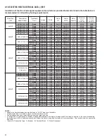
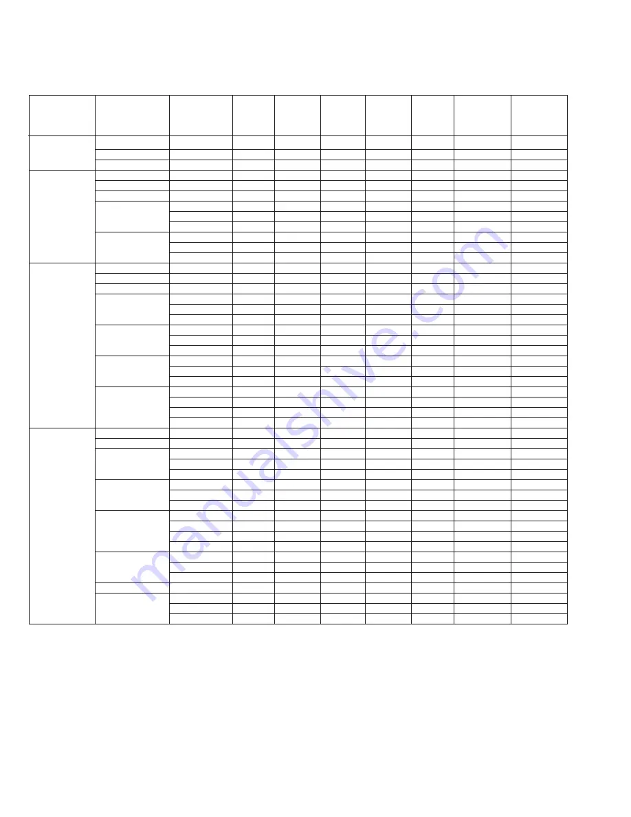
4.10 ELECTRIC HEAT ELECTRICAL DATA (-)H2V
Installation of the UL Listed original equipment manufacturer provided heater kits listed in the table below is
recommended for all auxiliary heating requirements.
Summary of Contents for RH1V2417STANJA
Page 54: ...54 FIGURE 44 COMFORT CONTROL2 SYSTEM AIR HANDLER WIRING DIAGRAM H2V...
Page 55: ...55...
Page 56: ...56 CM 0115...


