24
5.0 AIR HANDLER EQUIPPED WITH ECM
MOTOR INTERFACE CONTROL BOARD (-)H1V
IMPORTANT:
Factory switch settings are all “OFF” except switch 9, which is “ON”.
5.1 ECM MOTOR INTERFACE CONTROL AND SETTINGS
IMPORTANT:
Disconnect power to air handler when changing DIP switch positions. Even if
blower is not operating, the motor will not recognize changes in DIP switch positions until unit
power is removed and then restored.
The (-)H1V series air handlers have ECM blower motors, which deliver a constant level of air-
flow over a wide range of external static pressures (up to 1.0" W.C.). The interface board pro-
vides the required communications between the thermostat and the ECM blower motor. The
(-)H1V series of air handlers feature:
• An automotive-style ATC blade fuse for transformer protection (3 amp).
• An on-board LED to indicate blower CFM.
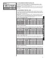
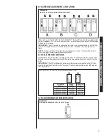
There is a bank of 10 DIP switches on the interface board that define the operation of the
ECM motor (see Table 1).
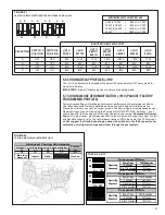
Refer to Figure 23 for switch identification and factory default settings.
NOTE:
All units are shipped from the factory on High Airflow.
FIGURE 23
ECM MOTOR FACTORY SETTINGS
TABLE 1
SWITCH FUNCTIONS
Switch
Function
1 & 2
Cooling Airflow Settings
3 & 4
Cooling Airflow Adjustment
5 & 6
Heating Airflow Settings
7 & 8
Cooling Delay Profiles
9 & 10
On-Demand Dehumidification – Active & Passive
Summary of Contents for RH1V2417STANJA
Page 54: ...54 FIGURE 44 COMFORT CONTROL2 SYSTEM AIR HANDLER WIRING DIAGRAM H2V...
Page 55: ...55...
Page 56: ...56 CM 0115...


