37
C
O
N
V
E
N
T
IO
N
A
L
T
H
E
R
M
O
S
T
A
T
W
IR
IN
G
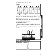
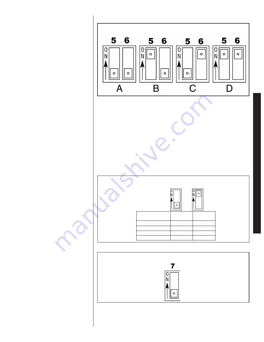
6.13 AIRFLOW ADJUSTMENT (-)H2V (TRIM)
When not using the
Comfort Control
2
System™
, the (-)H2V air handler cooling airflow
can be t/-10% to suit the installation. To adjust the airflow, adjust DIP switches
5 and 6 per this table:
IMPORTANT:
The DIP switches are active only when using conventional a 24VAC ther-
mostat. If using the
Comfort Control
2
System™
, refer to Section 5.4 for adjusting air-
flows.
NOTE:
Airflow adjustment is active for cooling operation only. Cooling airflow adjust-
ments are ignored when electric heat is activated.
6.14 ELECTRIC HEAT AIRFLOW
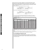
The RHPN-series air handlers are shipped with the “Low KW airflow” feature turned OFF.
Activate lower airflow feature for lower KW electric heat applications by turning DIP switch
8 ON.
IMPORTANT:
The DIP switches are active only when using a conventional 24VAC ther-
mostat. If using the
Comfort Control
2
System™
, refer to section 5.5 for low KW heat air-
flow adjustment.
6.15 COOLING MODE DEHUMIDIFICATION
FIGURE 33
DIP SWITCH SETTING FOR AIRFLOW ADJUSTMENTS
FIGURE 34
ON DEMAND DEHUMIDIFICATION DIP SWITCH (-)H2V
ELECTRIC HEAT AIRFLOW FOR THE RHPN AIR HANDLERS (-)H2V
RH2V2421HTACJA00
800 CFM
600 CFM
RH2V3624HTACJA00
1200 CFM
600 CFM
RH2V4824HTACJA00
1600 CFM
800 CFM
RH2V6024HTACJA00
1800 CFM
800 CFM
Air Handler
Model
Above
15KW:
15KW and
below:
To adjust the
a
To adjust the
a
8
8
Summary of Contents for RH1V2417STANJA
Page 54: ...54 FIGURE 44 COMFORT CONTROL2 SYSTEM AIR HANDLER WIRING DIAGRAM H2V...
Page 55: ...55...
Page 56: ...56 CM 0115...


