38
C
O
N
V
E
N
T
IO
N
A
L
T
H
E
R
M
O
S
T
A
T
W
IR
IN
G
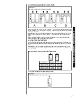
The (-)H2V series air handler is shipped with “On Demand Dehumidification” (ODD)
turned OFF. On Demand Dehumidification is used in conjunction with a traditional
24VAC thermostat equipped with an on-board humidity sensor. Activate ODD by turning
DIP switch 7 ON. ODD operation is controlled by the indoor humidity sensed at the ther-
mostat. Operation is:
Normal Humidity (humidity BELOW the thermostat set point):
High Humidity (humidity ABOVE the thermostat set point):
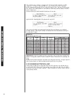
The (-)H2V air handler is programmed to provide maximum efficiency and optimum
humidity removal. When high humidity is detected, the air handler reduces cooling air-
flow defined in Table 6.
IMPORTANT:
The DIP switches are active only when using conventional a 24VAC ther-
mostat. If using the
Comfort Control
2
System™
, refer to Section 5.4 for adjusting air-
flows.
NOTE:
ODD airflow adjustments are active for cooling operation only. They are ignored
when the heat pump is in heating mode or when electric heat is activated.
6.16 COOLING DELAY PROFILES (-)H2V
Cooling delay profiles are not available when the H2V air handler is controlled using a
conventional 24VAC thermostat. These profiles are available only when the air handler
is wired for the
Comfort Control
2
System™
. Refer to Section 5.4 for the
Comfort Control
2
Cooling Delay Profiles.
TABLE 12
ODD AIRFLOW REDUCTION (-)H2V
Airflow (CFM)
2nd Stage (Y2) 1st Stage (Y1)
Switch 2
Position
Switch 1
Position
Outdoor
Unit
(-)H2V
2421HT
(-)ASL-025
OFF
OFF
650
500
3624HT
(-)ASL-037
ON
OFF
950
750
3624HT
(-)ASL-039
OFF
OFF
950
650
4824HT
(-)ASL-048
OFF
OFF
1275
800
6024HT
(-)ASL-060
OFF
OFF
1350
850
2421HT
(-)ARL-025
ON
OFF
650
500
3624HT
(-)ARL-038
ON
OFF
950
750
4824HT
(-)ARL-049
ON
OFF
1275
950
6024HT
(-)ARL-061
ON
OFF
1350
1025
O
Normal Humidity
Result
A 24VAC signal is applied to
the ODD terminal
Full rated airflow is delivered
by the blower
O
High Humidity
Result
No signal applied to the ODD
terminal
Airflow is reduced by a preset
amount to increase latent
capacity
Summary of Contents for RH1V2417STANJA
Page 54: ...54 FIGURE 44 COMFORT CONTROL2 SYSTEM AIR HANDLER WIRING DIAGRAM H2V...
Page 55: ...55...
Page 56: ...56 CM 0115...


