40
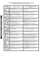
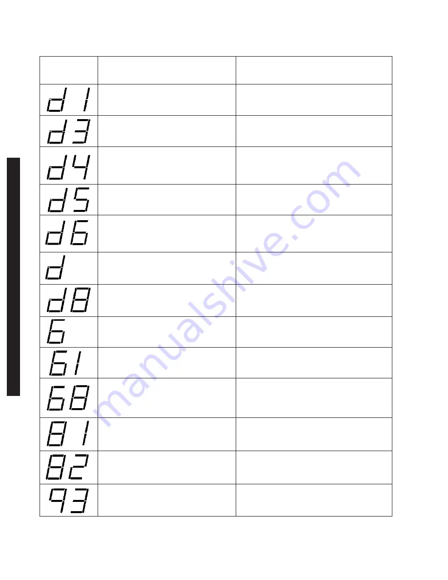
6.18 AIR HANDLER DIAGNOSTIC CODES (-)H2V (continued)
Descriptions of the ICC diagnostic codes are provided below:
T
T
7-Segment
LEDs Display
Code
Diagnostic Description
d1 – No Shared Data
The control board does not have shared data.
• Replace memory card with correct system
information
d3 – Airflow CFM Mismatch
The air handler cannot supply the required
airflow for proper system operation
• Misapplied/wrong indoor air mover – replace
with properly sized air handler/furnace.
Status/Possible Cause – Troubleshooting
Information
T
d4 – (Device) Memory Card Invalid for
Device
The memory card is missing or the data in the
memory card does not match the data in the
control.
• Check memory card to ensure it matches
device
• Check if memory card is present
T
d5 – Card Hardware Conflict
The motor horsepower is not correct for the
air handler
• Replace the air handler motor with the correct
horsepower motor.
• Replace the memory card with correct system
information.
T
d6 – BLWR HP CNFLCT
Blower Horsepower conflict
The horsepower data in the memory card
does not match the motor horsepower.
• Replace the motor with correct horsepower
motor.
• Replace the memory card with correct system
information. Check memory card to ensure
it matches device
T
d8 – Old Shared Data
System data is obsolete
• If system will not operate, order new memory
card to update system information.
T
T
T
T
68 – ECM No Signal
The ECM motor is not communicating to
the air handler control board.
• Make sure the ECM motor wiring harness is
plugged into the ECM motor and control
board.
• Test the ECM motor for proper operation using
a service tool.
T
T
81 – Return Air Sensor Out of Range
The resistance of the sensor out of range for
normal operation.
• Make sure the sensor is plugged into the air
handler control board.
• Check the resistance of the sensor. Replace if
it is out of tolerance.
T
82 – Supply Air Sensor Out of Range
The resistance of the sensor out of range for
normal operation.
• Make sure the sensor is plugged into the air
handler control board.
• Check the resistance of the sensor. Replace if
it is out of tolerance.
T
93 – Internal Control Fault
The air handler control is not functioning.
• Check control for proper system operation.
• Replace control
60 – BLWR FLT–RUN
The ECM motor is running but has a
fault
• TEST the ECM for proper operation.
0
61 – BLWR FLT–NO RUN
The ECM motor is not operating
• Make sure the ECM motor wiring harness is
plugged into the ECM motor and control board.
• Test the ECM motor for proper operation.
T
d7 – BLWER MFG CNFLCT
The System does not have any data on the
installed motor.
• Replace the memory card with correct system
information.
7
C
O
N
V
E
N
T
IO
N
A
L
T
H
E
R
M
O
S
T
A
T
W
IR
IN
G
Summary of Contents for RH1V2417STANJA
Page 54: ...54 FIGURE 44 COMFORT CONTROL2 SYSTEM AIR HANDLER WIRING DIAGRAM H2V...
Page 55: ...55...
Page 56: ...56 CM 0115...


