49
• Loosen the bolt holding the wire motor band around the motor shell and pull the
motor from the motor mount. Note the motor position in the mount for re-assembly.
• To re-assemble, insert the motor shaft through the hub in the blower wheel and orient
the motor to original position.
• For proper motor cooling, it is important that the motor be mounted the same as the
original, as far into the blower as practical.
• The dimension from the face of the motor end plate (shaft end) to the first wire on the
motor mount band around the shell should be:
DIMENSION
TONNAGE
CABINET SIZE
1
3
/
32
"
1
1
/
2
& 2
17
1
1
/
2
"
2
1
/
2
& 3
17
2
1
/
2
"
3, 3
1
/
2
& 4
21
2
7
/
8
"
5
24
• With motor held to above position and motor lead plugs oriented to the original posi-
tion (the wire connectors on the motor must point straight to the supply air end of the
unit and away from the return air [filter] end of the unit). Securely tighten the bolt on
the mount band to the motor shell.
• Turn the motor shaft so that the flat on the shaft is located under blower wheel
setscrew, and the blower wheel is centered in the blower housing with the same dis-
tance on each side between the inlet venturi and the outside of the blower wheel.
• Re-assemble the motor wiring (high and low voltage plugs) into the motor.
IMPORTANT:
DO NOT FORCE POWER PLUG INTO THE MOTOR CONNECTOR
BACKWARDS. The A.C. power plug to the motor has locking tabs. It has been
proven that by applying excessive force to the A.C. cable half of the connector it is
possible to force the connector in backwards. It will not seat and “click” properly but
will make connection. If A.C. power is applied with the connector reversed the motor
will be immediately destroyed.
13.8 ECM CONTROL MODULE REPLACEMENT
Always take the following steps before replacing the control module on the end of the
ECM indoor blower motor.
1.
HAVE THE CORRECT REPLACEMENT MODULE.
These controls are factory pro-
grammed for specific operating modes. Even though they look alike, different mod-
ules may have different CFM characteristics.
IMPORTANT:
Using the wrong control module voids all product warranties and may pro-
duce unexpected results.
2. Turn off power to the equipment. Wait at least 5 minutes after disconnecting AC
power before opening the motor.
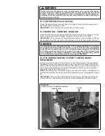
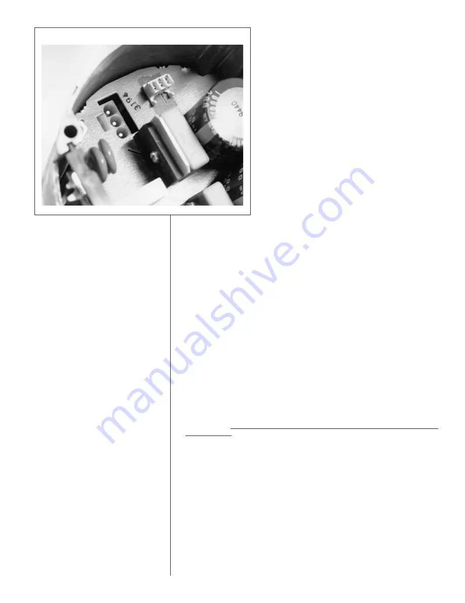
FIGURE 39
INTERNAL MOTOR PLUG AND SOCKET
Summary of Contents for RH1V2417STANJA
Page 54: ...54 FIGURE 44 COMFORT CONTROL2 SYSTEM AIR HANDLER WIRING DIAGRAM H2V...
Page 55: ...55...
Page 56: ...56 CM 0115...

