12
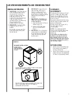
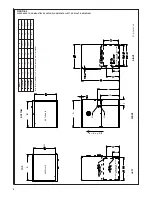
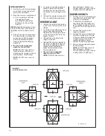
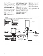
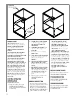
FIGURE 7
POSITION ORIENTATION
ST-A1242-05-X0
UPFLOW UNITS
1. Position the unit to minimize long
runs of duct or runs of duct with
many turns and elbows.
2. Open the return air compartment.
a. Cut an opening in the side.
The opening should
be cut the full width of the
knockouts on the unit. See
Figure 5.
NOTE:
Where the maximum air flow
is 1800 CFM or more, both sides or
the bottom must be used for return
air.
3. Connect the return duct or return
air cabinet to the unit. Make the
connection air tight to prevent
entraining combustion gases
from an adjacent fuel-burning
appliance.
4.
Be sure to have adequate
space for the unit filter.
NOTE:
DO nOT take return air
from bathrooms, kitchens, air
handler rooms, garages, utility or
laundry rooms, or cold areas.
NOTE:
DO nOT use a rear air
return.
5. If summer air conditioning (heat
pump) is desired, position the
indoor coil on the top of the unit.
Insure that no air can bypass this
coil.
6. Connect the supply air plenum to
the air handler plenum opening.
HORIZONTAL UNIT
1. Position the unit to minimize long
runs or runs with many turns and
elbows.
2. If summer air conditioning or heat
pump is desired, position the
indoor coil on the supply air end
of the unit. Insure that no air can
bypass this coil.
3. Connect the air handler to the
supply air plenum.
4. Connect the return air ducting to
the return air opening of the unit.
Make the connection air tight to
prevent pulling combustion
gases from an adjacent fuel-
burning appliance.
5.
Be sure to have adequate
space for the unit filter.
NOTE:
DO nOT take return air
from bathrooms, kitchens, air
handler rooms, garages, utility or
laundry rooms, or cold areas.
DOWNFLOW UNITS
1. Position the unit to minimize long
runs of duct or runs of duct with
many turns and elbows.
2. If summer air conditioning is
desired, position the indoor coil
on the supply air side of the unit.
Insure that no air can bypass this
coil.
3. Connect the furnace to the
supply air plenum.
4. Connect the return air ducting to
the return air opening at the top
of the unit. Make the connection
air tight to prevent entraining
combustion gases from an
adjacent fuel-burning appliance.
5. Be sure to have adequate space
for the unit filter.
NOTE:
DO nOT take return air
from bathrooms, kitchens,
furnace rooms, garages, utility or
laundry rooms, or cold areas.
Summary of Contents for RW1P
Page 29: ...29 FIGURE 21 ELECTRICAL WIRING DIAGRAM PSC MOTORS RW1P...
Page 32: ...32 FIGURE 24 ELECTRICAL WIRING DIAGRAM...
Page 33: ...33...
Page 34: ...34...
Page 35: ...35...
Page 36: ...36 CM 0617...


