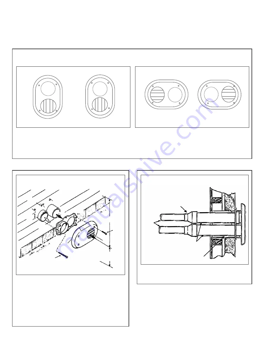
Use the vent plate as a template to locate the vent and air
intakes holes and four mounting holes. Cut two 3-7/8 inch
diameter holes for the vent and air intake openings. Drill four
3/16
ⴖ
diameter holes for inserting the plastic anchors into the
wall. Attach the vent plate to the wall with four screws (#8
pan, 2
ⴖ
long, SMS Type A18-8 stainless steel).
Assemble the vent cap to the vent plate. Insert the four (#8
pan, 1
ⴖ
long, SMS Type A18-8 stainless steel) screws into
the vent cap screw hole openings and securely attach the
vent cap to the vent plate.
INSTALLATION - Side Wall Vent Kit
IMPORTANT:
Refer to Furnace or Condensing Tankless Water Heater Installation Instructions for complete information on installation
of Side Vent Kit. (See Figures 1-3.) All applicable codes should be followed when determining vent location.
2
FIGURE 2
TYPICAL SIDE WALL APPLICATION
FIGURE 3
TOP VIEW – TYPICAL INSTALLATION
ANCHORS
(4 req.)
COMBUSTION
AIR
VENT
VENT
PLATE
VENT
CAP
VENT
2" SCREWS
(4 req.)
MAINTAIN 12" (18" FOR CANADA) MINIMUM
CLEARANCE ABOVE HIGHEST ANTICIPATED
SNOW LEVEL OR GRADE WHICHEVER IS GREATER
1" SCREWS
(4 req.)
2", 2-1/2"
or 3" PIPING
SEAL ALL
WALL CAVITIES
3" PIPING
REDUCING
COUPLING,
FIELD SUPPLIED
IF NEEDED
12" MINIMUM
TO OVERHANG
2.53"
4.
53
"
4.
53
"
FIGURE 1
VENT KIT INSTALLATION OPTIONS
OPTION B
TYPICAL HORIZONTAL INSTALLATION
NOTE:
Install the vent and air intake piping into the vent plate openings. Seal all gaps between the pipes and wall. Use silicon
sealant to seal the vent pipe to the vent cap to permit field disassembly for cleaning. Also seal all pipe penetrations in wall. To pre-
vent possibility of condensate freeze-up, do not install vent kits one above the other.
NOTE:
Reducing couplings are required, but not supplied,
for pipe reduction.
CM 0111
OPTION A
TYPICAL VERTICAL INSTALLATION


