CONNECTIONS
–
PLUMBING
36
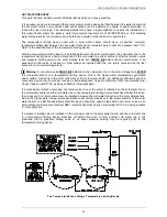
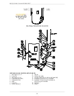
This water heater has either a plastic dip tube or fitting liner in the inlet
and outlet fittings (see diagram). These must be in place for the water
heater to function properly. Do not remove or damage them by using
heat nearby. They will be pushed into the correct position as the fitting
is screwed in.
PIPE SIZES
To achieve true mains pressure operation, the cold water line to the
water heater should be the same size or bigger than the hot water line
from the water heater.
The pipe sizing for hot water supply systems should be carried out by persons competent to do so, choosing
the most suitable pipe size for each individual application. Reference to the technical specifications of the
water heater and local regulatory authority requirements must be made.
IN-SERIES BOOSTER (IF INSTALLED)
The pipe work between the solar storage tank and an in-series booster has a minimum recommended pipe
size of DN20,
MUST BE
of copper and be fully insulated with a closed cell type insulation or equivalent and
in accordance with the requirements of AS/NZS 3500.4. The insulation must be weatherproof and UV
resistant if exposed. The insulation must be fitted up to the connections on both the solar storage tank and
the in-series booster.
An isolation valve must be installed on the water line to the in-series booster. The isolation valve must be of
a full flow type if the in-series booster is a continuous flow water heater.
TEMPERATURE PRESSURE RELIEF VALVE
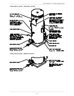
The temperature pressure relief valve is shipped either under the top flap of the water heater carton or
behind the front cover. The temperature pressure relief valve must be fitted before the water heater is
operated. Before fitting the relief valve, make sure the probe has not been bent. Seal the thread with Teflon
tape - never hemp. Make sure the tape does not hang over the end of the thread.
Screw the valve into the correct opening
(refer to the installation diagram on page
27
)
leaving the valve
outlet pointing downwards. Do not use a wrench on the valve body - use the spanner flats provided. A
copper drain line must be fitted to the temperature pressure relief valve (refer to
"Relief Valve Drain"
on
page 37).
The valve must be insulated with closed cell polymer insulation or similar (minimum thickness 9 mm) and the
insulation installed so as not to impede the operation of the valve. The insulation must be weatherproof and
UV resistant if exposed.
EXPANSION CONTROL VALVE
Local regulations may make it mandatory to install an expansion control valve (ECV) in the cold water line to
the water heater. In other areas, an ECV is required if the saturation index is greater than +0.4 (refer to
“Water Supplies”
on page 14).
The expansion control valve must always be installed after the non return valve and be the last valve
installed prior to the water heater
(refer to diagrams on page
35
)
. A copper drain line must be fitted to the
expansion control valve (refer to
"Relief Valve Drain"
on page 37).
The valve must be insulated with closed cell polymer insulation or similar (minimum thickness 9 mm) and the
insulation installed so as not to impede the operation of the valve. The insulation must be weatherproof and
UV resistant if exposed.


