38
CONNECTIONS
–
ELECTRICAL
The power supply to the water heater must not be switched on until the water heater is filled with
water
and a satisfactory megger reading is obtained.
All electrical work and permanent wiring must be carried out by a qualified person and in accordance with the
Wiring Rules AS/NZS 3000 and local authority requirements.
If this water heater is installed with an in-series booster, then the electric booster heating unit will not need to
be connected to a power supply and the references to the electric booster heating unit, thermostat and
boosting controls in these installation instructions will not be applicable to the installation.
Note:
AS 3498 requires that a water heater provides the means to inhibit the growth of Legionella bacteria in
potable water. This water heater can satisfy this AS 3498 requirement provided the electric booster is
energised for a sufficient period each day and the electric booster thermostat setting is 60°C or higher.
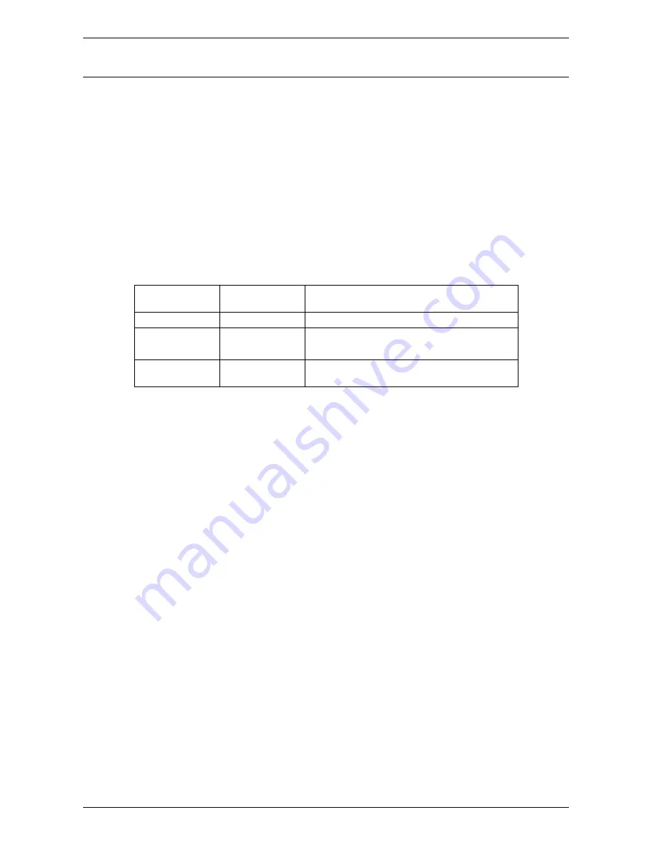
The power consumption of the water heater is:
Component
Power
consumption
Comments
Solar controls
4 Watts
Constant load - differential controller
Solar circulator
36 Watts
Maximum load at solar heating cycle start up
30 Watts
Average load during the solar heating cycle
Heating unit
2400 or 3600 or
4800 Watts
Load when heating unit is operating
The water heater will only operate on a sine wave at 50 Hz. Devices generating a square wave cannot be
used to supply power to the water heater.
SOLAR STORAGE TANK
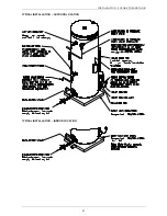
The solar storage tank with an electric booster heating unit must be directly connected to a 240 V AC 50 Hz
mains power supply with an isolating switch installed at the switchboard.
The power supply can be either a continuous, or a time of use, or an extended Off-Peak (overnight and day)
or an Off-Peak (overnight) electricity supply. Discuss the power supply requirements with the householder.
A flexible 20 mm conduit is required for the electrical cable to the solar storage tank. The conduit is to be
connected to the unit with a 20 mm terminator. Connect the power supply wires directly to the terminal block
and earth tab connection, ensuring there are no excess wire loops inside the front cover.
THERMOSTAT SETTING
The thermostat is adjustable from 60°C to 70°C. The thermostat is adjusted by turning the adjuster
anticlockwise to decrease the temperature setting and clockwise to increase the temperature setting. Only
adjust the temperature setting when the isolating switch is switched off at the switchboard.
For reasons of safety and economy, we advise the thermostat be set at the lowest temperature that will
provide sufficient hot water during periods when boosting is required. Rheem recommends the thermostat is
set at 60°C to maximise solar contribution. Discuss the thermostat setting requirements with the
householder.
SOLAR CONTROL UNIT
The solar control unit, supplied with a 1.8 metre power cord, requires a switched 240 V AC 50 Hz general
purpose outlet (GPO) to be located within 1.2 metres of the installation. The GPO must have a continuous
power supply originating from a circuit other than the water heater circuit. The GPO is required to be
weatherproof if installed outdoors.


