16
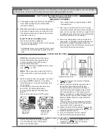
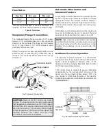
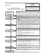
Gas Pressure
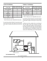
Test at Gas Valve
Gas Pressure
Test at
H
eater
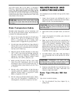
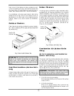
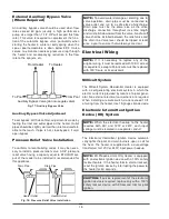
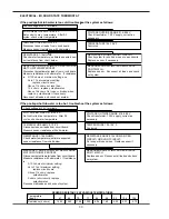
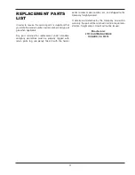
Gas Pressure Adjustment
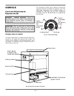
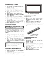
Fig. 11: Gas Pressure Testing Locations
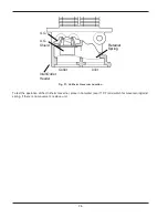
Fig. 12: Robertshaw Millivolt Valve
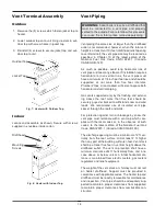
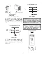
Gas Pressure Adjustment
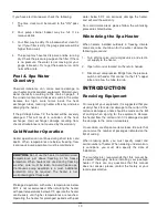
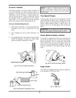
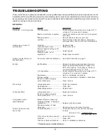
Fig. 13: Honeywell Millivolt Valve
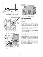
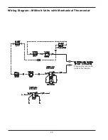
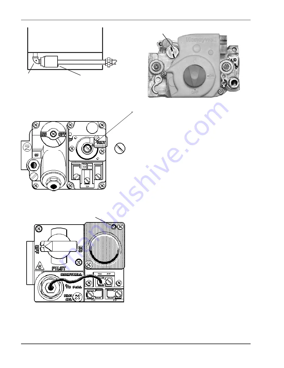
Gas Pressure
Adjustment
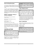
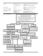
Fig. 14: Honeywell IID Valve
Plumbing for Water
Connections
Location
The VERSA heater requires water flow and positive
pressure to fire and operate properly. It must therefore
be installed downstream of the discharge side of the
filter pump. A typical installation is plumbed as follows:
1. The inlet side of the filter is plumbed directly to the
discharge side of the filter pump:
2. The outlet side of the filter is then plumbed to the
inlet of the heater; and
3. The outlet of the heater is plumbed to the return
line to the spa. The pump, filter and heater are
thus plumbed in series.
Plumbing from the heater back to the spa must not
have any valves or restriction that could prevent flow
when the pump is operating. To do so will void the war-
ranty.
Heater must be located so that any water leaks will not
damage the structure of adjacent area. High tempera-
ture plastic pipe (CPVC) may be connected directly
into the heater if local codes permit.


