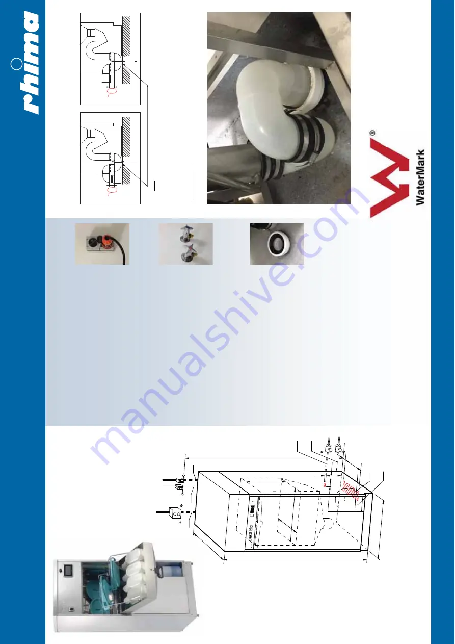
Floor and wall installation of the drain.
Please note: Failure to set this distance correctly can cause unit to malfunction.
*
WATERMARK
LICENSE
WM-022073
ATS
5200.104
This
appliance
incorporates
back
flow
prevention
complying
with
AS
3500.1.
No
further
back
flow
protection
is
required
for
connection
to
the
water
supply.
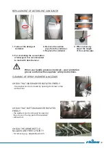
1.
ELECTRICITY
240/415V
AC,
3-phase
+
Neutral,
20Amp
Please
note:
Plug
NOT
included
- Must
be
connected
using
a
disconnect
device.
A
plug
MAY
be
fitted
to
the
m
a
ch
in
e a
t a
n e
xt
ra c
os
t. A
t t
he
ti
m
e
o
f t
he
installation
check
the
motor
direction.
(International
wiring
rules
apply)
2.
COLD
WATER
Flexible
inlet
hose
with
R½”
female
thread,
L = 2 m (
M
in
5
°C - M
a
x 2
5°
C
)
Water
flow
rate:
Min
100kPa
- Max
600kPa
3.
HOT
WATER
Flexible
inlet
hose
with
R½”
female
thread,
L = 2 m (
M
in
6
5°
C - M
a
x 8
0°
C
)
Water
flow
rate:
Min
100kPa
- Max
600kPa
4.
WASTE
OUTLET
Ø110
mm
(hatched
area
for
centre
of
the
pipe)
D
ra
in f
lo
w
ra
te
2
ltr / S
ec
, “
S”
o
r “
P” t
ra
p
in
sid
e
machine.
Max
discharge
temp
65°C.
5.
STEAM
- For
steam
heated
model
ONLY
Steam,
flexible
steel
armoured
inlet
hose
with
R½”
male
thread,
L
=
1,2
m
6.
CONDENSATE
- For
steam
heated
model
ONLY
Flexible
steel
armoured
inlet
hose
with
R½”
male
thread,
L = 1
,2 m
.
7.
SUCTION
HOSE
and
place
for
detergent.
Wall
anchors
will
be
supplied
&
must
be
installed
by
purchaser.
ONLY
ROOM
VENTILLATION
REQUIRED.
Note: There must be a space of 5mm between the plastic water trap and the floor.
70
70
Ø90
Ø90
*
*
S - Trap
(Floor connection)
Detail A
D
etail B
P - Trap
(Wall connection)
1
3
2
5
6
4
7
600
1450±10
200
90
90
40
140
60
20
195
480
360
340
1800±100
630
RHIMA DEKO 190
TECHNICAL SPECIFICATIONS
A typical drain connection
pictured (above)
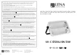
Deko 190iX
pictured
RHIMA AUSTRALIA PTY LTD PH: 1800 659 292 or WWW.RHIMA.COM.AU
Dimensions
pictured
Placement:
A minumum clearance of 20mm either side of the
machine is recommended.
Maintenance:
If possible for cleaning and maintenance a
200-300mm clearance either side is preferred.


