

11
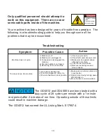
Paper Jam:
u
The OD4012 and OD4000 punches use a circuit board for controlling
the punch cycle, this circuit board also has the ability to automatically
reverse the pusher bar and punch pins to their starting position if the
machine takes too much time to complete a punch cycle. This
condition could happen if too much material has been attempted to be
punched at one time. If this condition occurs, allow the machine to
attempt to reset itself back to its home position.
u
If the punch does not reset itself back to its home position, the punch
will need to be reversed manually.
!
WARNING
Crush hazard.
Keep hands away
from moving parts.
Lockout and disconnect
power before servicing.
u
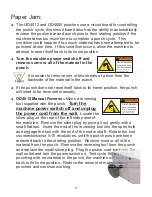
Turn the machine power switch off and
remove some or all of the material in the
punch.
It is easier to remove one or two sheets at a time from the
backside of the material in the punch.
u
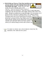
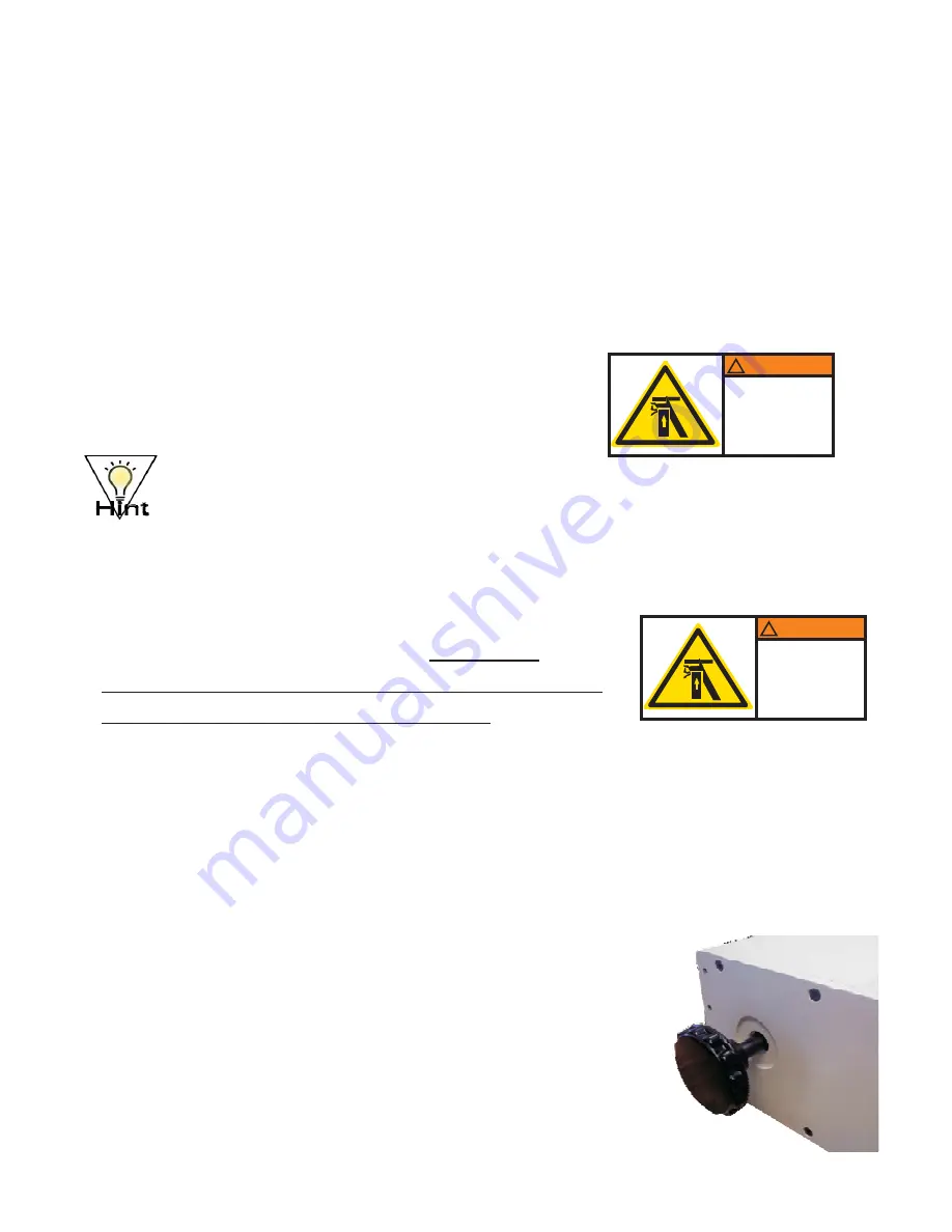
OD4012 Manual Reverse
utilizes a reversing
tool supplied with the punch.
Locate the
silver plug on the rear of the left side panel of
the machine. Remove the silver plug by prying it out gently with a
small flat tool. Insert the end of the reversing tool into the open hole
and engage the tool with the end of the motor shaft. Rotate the tool
counterclockwise 5-10 revolutions, until the punch pins have been
retracted back to the starting position. Remove most or all of the
material from the punch. Remove the reversing tool from the punch
and replace the small silver plug. Plug the power cord back into the
wall outlet and turn the power switch on. Test cycle the machine by
punching with no material in the punch, the machine will reset itself
back to its home position. Reduce the amount of material being
punched and continue working.
Turn the
machine power switch off and unplug
the power cord from the wall.
!
WARNING
Crush hazard.
Keep hands away
from moving parts.
Lockout and disconnect
power before servicing.
Summary of Contents for OD4000
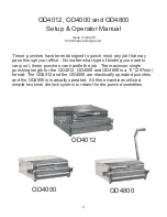
Page 1: ...Instruction Book for the OD4012 OD4000 and OD4800 ...
Page 4: ......


