4
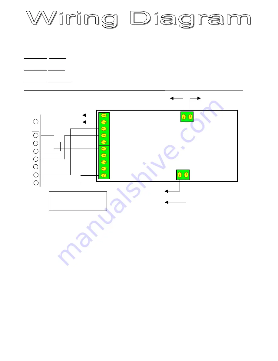
Typically, this unit should be wired up in the following configuration on a Penta system.
The Penta PGM output must be programmed as an ARMED output
Address 10 Data 01
(for Penta software version 4A123)
Exit delay should be programmed to 0 seconds
Address 08 Data 00
(for Penta software version 4A123)
The Tamper zone must be programmed as an ARM/DISARM zone
Address 01 Data 11000 First digit indicates number of keypads
(for Penta software version 4A123)
SPECIAL NOTE:
This setup is designed for use with the PENTA control panel.
When using this module you will not be able to use the PGM output for the strobe to latch on after an
alarm condition. The strobe must now be wired in parallel with the siren output so that it flashes only when
the siren sounds.
To pin 3 (+12V)
To pin 4 (- NEG)
16
15
14
13
12
11
10
Note: 2k2 end of line
resistors are build into the
receiver!
Pin 8 (- Siren)
Pin 4 (- Neg)
Pin 9 (- PGM)
Not Used


