10
2.2. Installing and Wiring The Main Unit
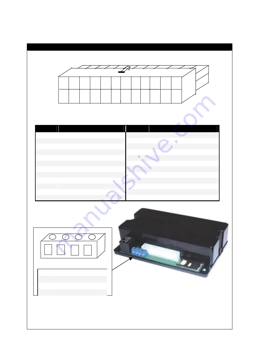
Harness Connections
Figure 2
PIN No
CONNECTION
PIN No
CONNECTION
1
Immobiliser 2a (8Amp)
13
Immobiliser 2b (8Amp)
2
Immobiliser 2b (8Amp)
14
Immobiliser 2a (8Amp)
3
Door Switch (Neg Types)
15
Negative Alarm
4
Bonnet Trigger (Neg Sw.)
16
Auxiliary input
5
Dummy Wire, Not used.
17
Boot input
6
Siren trigger
18
Immobiliser 1 (8Amp)
7
Boot Release Output
19
Immobiliser 1 (8Amp)
8
Negative Out on Arm
20
Negative Pulse Lock
9
Ignition Input
21
Positive LED
10
Neg Pulse Unlock
22
Negative LED
11
Right Indicator
23
Ground
12
Left Indicator
24
+12V power
SMS Controlled Relay Output is a 150mA Negative Output when activated
i.e. ‘ONOUT1’ Refer to section 2.8.15. SMS Controlled Relay Output
1 2 3 4 5 6 7 8 9 10 11 12
13 14 15 16 17 18 19 20 21 22 23 24
1 2 3 4
1
SMS Relay Output3
2
Not Used
3
SMS Relay Output1
4
SMS Relay Output2
Summary of Contents for RAMV2
Page 37: ...37 This page intentionally blank...
Page 38: ...38 This page intentionally blank...
Page 39: ...39 This page intentionally blank...
Page 40: ...40...


