background image

OPERATION

RC115/118/120/125   02/12

Operation Section 4-23

© 2012 Alamo Group Inc.

OPERA

T

ION

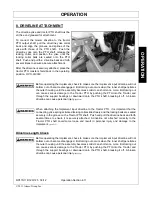
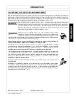
When confronted with an incline or ditch, do not
approach from an angle which is perpendicular or
straight on as damaged to over collapse of the
driveline may occur.

When crossing such terrain, the implement should
be fully lowered for a lower center of gravity and
added stability.  

OPS-R-0021

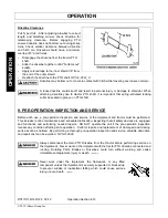
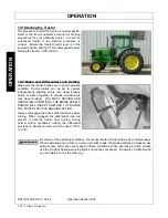
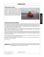
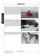
Inclines and ditches should be approached along a
line which is at an angle as shown.  This type of
path will reduce the possibility of over-collapse of
the driveline and resulting damage.  If the gradient
is so steep that such an approach increases the
possibility of a tractor roll-over, select an alternate
crossing path. 

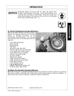
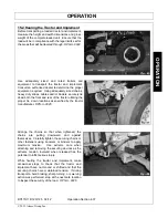
When operating the tractor and mower across
slopes and inclines, through ditches, and other
uneven terrain conditions, it is important to maintain
sufficient deck to ground clearance.  Blade contact
with the ground may cause soil, rocks and other
debris to be thrown out from under the mower
resulting in possible injury and/or property damage.
Ground contact also produces a severe shock load
on the mower drive and to the mower blades
resulting in possible damage and premature wear.

OPS-R-0022

Summary of Contents for RC 115

Page 1: ...L 60936 800 446 5158 Email parts servis rhino com FLAIL SHREDDER This Operator s Manual is an integral part of the safe operation of this machine and must be maintained with the unit at all times READ...

Page 2: ...ual before operating this equipment Do not allow anyone to operate this equipment who has not fully read and understood this manual Contact your Dealer to explain any instructions that you do not full...

Page 3: ...anual or if you have any questions concerning safety of operation contact your supervisor dealer or Alamo Group Ag If you would like a VHS video tape of the video please email AEMVideo alamo group com...

Page 4: ...________________________________________ City _____________________________________ State ____________________________________ Zip Code _________________________________ Mower Model __________________...

Page 5: ...that operator is responsible for keeping clear of such hazards PRE DELIVERY SERVICE CHECK AND ADJUST OR LUBRICATE AS REQUIRED See Operator s Manual for Details Inspection Performed Warranty and Safety...

Page 6: ......

Page 7: ...15 Decal Description 1 17 Federal Laws and Regulations 1 25 INTRODUCTION SECTION 2 1 RHINO LIMITED WARRANTY 2 5 ASSEMBLY SECTION 3 1 SHIPPING STAND REMOVAL 3 2 CHECK OIL LEVEL 3 2 TONGUE ASSEMBLY INST...

Page 8: ...eed 4 27 Shutting Down the Implement 4 28 END TOW OPERATION 4 29 CONVERTING MACHINE FROM TRANSPORT TO OPERATION 4 31 Lift or Semi Mount Configuration 4 31 End Tow Operation Pull Type Model 4 31 CONVER...

Page 9: ...RIVELINE CAT 4 SAFETY SHIELD 5 16 Flail Blades Inspection 5 17 General Information on Flail Shredder Vibration 5 18 STORING THE RC115 118 120 125 5 19 Pre season Check 5 19 PROPER TORQUE FOR FASTENERS...

Page 10: ......

Page 11: ...Safety Section 1 1 2012 Alamo Group Inc SAFETY SECTION...

Page 12: ...ting this equipment Indicates an imminently hazardous situation that if not avoided WILL result in DEATH OR VERY SERIOUS INJURY Indicates an imminently hazardous situation that if not avoided COULD re...

Page 13: ...d operation can cause fatigue STOP and REST GENERAL OPERATING SAFETY VISIBILITY CONDITIONS WHEN MOWING OPERATE IN DAYLIGHT or with lights that gives at least 100 yards clear visibility BE ABLE TO SEE...

Page 14: ...locking balls in PTO shaft groove PUSH and PULL DRIVELINE on both the tractor and implement PTO SHAFTS to ensure it is SECURELY ATTACHED TO AVOID broken driveline during operations CHECK driveline fo...

Page 15: ...tip over KEEP BYSTANDERS CLEAR of area TO AVOID crushing LIFTED Equipment can fall from mechanical or hydraulic failure or inadvertent Control Lever movement TO AVOID EQUIPMENT FALLING while working...

Page 16: ...e cable rope chains and metal objects can be thrown or swing outside deck with great velocity 1 MARK objects that cannot removed 2 AVOID these objects when mowing HIGH GRASS and WEED AREA INSPECTION I...

Page 17: ...port position STOP MOWING immediately if blades strike heavy objects fixed structures metal guard rails and con crete structures 1 BLADES CAN FAIL from impact and objects can be thrown with great velo...

Page 18: ...on ONLY start tractor while seated in tractor seat ALWAYS BUCKLE UP seat belt when operating tractor and equipment ONLY OPERATE tractor and equipment while seated in tractor seat NEVER ALLOW RIDERS on...

Page 19: ...or missing ALWAYS REPLACE GUARDS that have been removed for service or maintenance Do Not use PTO or PTO guard as a step TO AVOID broken driveline during operations CHECK driveline for proper length...

Page 20: ...H FROM HIGH PRESSURE HYDRAULIC OIL LEAKS PENERATING SKIN DO NOT OPERATE equipment with oil or fuel leaks KEEP all hydraulic hoses lines and connections in GOOD CONDITION and TIGHT before applying syst...

Page 21: ...800 258 0808 for identify buried utility lines FIRE PREVENTION GUIDELINES while Operating Servicing and Repairing Mower and Tractor to reduce equipment and grass fire Risk EQUIP Tractor with a FIRE EX...

Page 22: ...eat ADJUST your operating position mirrors and implement transport for clear vision for traveling and traffic conditions PREPARE IMPLEMENT FOR TRANSPORTING OR TOWING DISENGAGE PTO RAISE MOWER REMOVE a...

Page 23: ...work FOLLOW manufacturer s instructions in handling oils solvents cleansers and other chemical agents DO NOT change any factory set hydraulic calibrations to avoid component or equipment failures DO...

Page 24: ...ades cuttershafts knives knife hangers rollers drivetrain components and bearings These parts are made and tested to Rhino specifications Non genuine will fit parts do not consistently meet these spec...

Page 25: ...o promote safe operation Damage to the decals may occur while in shipping use or reconditioning Rhino cares about the safety of its customers operators and bystanders and will replace the safety decal...

Page 26: ...T Lubrication Chart 16 00725720 1 INSTRUCT Belt Tension 17 nfs 1 SER PLT Serial Number Plate 18 00758194 2 WARNING Pinch Point 19 00775933 2 WARNING Guard Missing 20 1458393 2 REFLECT Amber Reflector...

Page 27: ...SAFETY RC115 118 120 125 02 12 Safety Section 1 17 2012 Alamo Group Inc SAFETY Decal Description...

Page 28: ...SAFETY RC115 118 120 125 02 12 Safety Section 1 18 2012 Alamo Group Inc SAFETY...

Page 29: ...SAFETY RC115 118 120 125 02 12 Safety Section 1 19 2012 Alamo Group Inc SAFETY...

Page 30: ...SAFETY RC115 118 120 125 02 12 Safety Section 1 20 2012 Alamo Group Inc SAFETY...

Page 31: ...SAFETY RC115 118 120 125 02 12 Safety Section 1 21 2012 Alamo Group Inc SAFETY...

Page 32: ...SAFETY RC115 118 120 125 02 12 Safety Section 1 22 2012 Alamo Group Inc SAFETY...

Page 33: ...SAFETY RC115 118 120 125 02 12 Safety Section 1 23 2012 Alamo Group Inc SAFETY...

Page 34: ...SAFETY RC115 118 120 125 02 12 Safety Section 1 24 2012 Alamo Group Inc SAFETY...

Page 35: ...sconnect the power source and wait for all machine movement to stop before servicing adjusting cleaning or unclogging the equipment except where the machine must be running to be properly serviced or...

Page 36: ......

Page 37: ...Introduction Section 2 1 2012 Alamo Group Inc INTRODUCTION SECTION...

Page 38: ...a minimum cutting height of 2 and keeping unprotected persons at a minimum distance of 300 feet from the shredder at all times during operation Safety is of primary importance to the owner operator a...

Page 39: ...e machine The RC flail Shredders are available with a Three point lift semi mount or pull type hitch in shredding widths of 12 15 18 20 and 25 25 pull or semi mount The shredder housing is a formed 3...

Page 40: ...d implement 2 Fill out the Warranty Card in full Be sure to answer all questions including the Serial Number of the implement Mail within 30 days of delivery date of this implement NOTE Warranties are...

Page 41: ...2 05 Purchaser is responsible for any labor charges exceeding a reasonable amount as determined by Manufacturer and for returning the goods to the Dealer whether or not the claim is approved Purchaser...

Page 42: ......

Page 43: ...Assembly Section 3 1 2012 Alamo Group Inc ASSEMBLY SECTION...

Page 44: ...ox and check oil level on dipstick a mark in the dipstick indicated correct oil level NOTE Use only Multi Purpose Gear Oil Rhino P N 00786250 or equivalent TONGUE ASSEMBLY INSTALLATION Pull Type Model...

Page 45: ...of link bar assembly item 3 to mounting point on top front of center plate Attach spacer item 5 to end of pin item 4 and fasten with 1 2 bolt item 6 and lock washer Asm FL 0068 3 Raise hitch with hoi...

Page 46: ...em 1 to wheel bar Item 2 with clamp plate Item 3 and four 3 4 bolts Item 4 lockwashers and nuts Items 5 6 Tighten bolts evenly and progressively torque to 200 ft lbs Attach ratchet screw jack p n 0055...

Page 47: ...AXLES 1 Mark desired row spacing with chalk Keep outer caster wheels as close to the outside as possible Fasten each caster wheel assembly with clamp plate and 4 bolts and locknuts 2 Attach cylinder...

Page 48: ......

Page 49: ...Operation Section 4 1 2012 Alamo Group Inc OPERATION SECTION...

Page 50: ...n inspected and foreign materials and debris have been removed PASSERSBY are inside enclosed vehicle This section of the Operator s Manual is designed to familiarize instruct and educate safe and prop...

Page 51: ...PM 12 000 FPM Rotor Speed 1900 RPM 1900 RPM 1900 RPM 1900 RPM Number of Knives 168 200 216 272 Driveline Size CAT 5 or 6 CAT 5 or 6 CAT 5 or 6 CAT 5 or 6 Hood Thickness 3 16 3 16 3 16 3 16 End Plate T...

Page 52: ...roved Personal Protective Equipment PPE for the job conditions when attaching operating servicing and repairing the equipment PPE is designed to provide operator protection and includes the following...

Page 53: ...ype Shredder Drawbar Extended 16 from PTO shaft end with safety chain attachment point for 21 Spline Output Shaft Drawbar Extended 20 from PTO shaft end with safety chain attachment point for 20 Splin...

Page 54: ...tires when flail is raised 20 of tractor weight should be on front tires Never stand between flail and tractor when coupling with quick hitch Remove or adjust drawbar to provide clearance for drivelin...

Page 55: ...proper operation and minimal wear to the driveline OPS R 0061_E DO NOT use a PTO adapter to attach a non matching Implement driveline to a Tractor PTO Use of an adapter can double the operating speed...

Page 56: ...h SG 10 Do not mount or dismount the Tractor while the tractor is moving Mount the Tractor only when the Tractor and all moving parts are completely stopped SG 12 4 2 Dismounting the Tractor Before di...

Page 57: ...n and service according to the tractor operator s manual Make sure all guards shields and other safety devices are securely in place The parking brake is on The PTO control lever is disengaged The 3 p...

Page 58: ...be held level by tractor lift while shredding Link float may be locked out by reversing center lock plate in link assembly This lock plate should only be used in level conditions and on tractors whic...

Page 59: ...shorten no more Bottoming out can cause serious damage to the Tractor PTO by pushing the PTO into the Tractor and through the support bearings or downward onto the PTO shaft breaking it off A broken d...

Page 60: ...in groove on PTO shaft 9 PRE OPERATION INSPECTION AND SERVICE Before each use a pre operation inspection and service of the implement and tractor must be performed This includes routine maintenance a...

Page 61: ...daily service and inspection Tire condition air pressure Wheel lug bolts Steering linkage PTO shield SMV sign is clean and visible Tractor s lights are clean and functional Tractor Seat belt is in go...

Page 62: ...E WITH SUBSEQUENT FAILURE AND POSSIBLY CAUSE SERIOUS INJURY FROM THROWN BLADES SGM 10 The operator s manual and safety signs affixed on the unit contain important instructions on the safe and proper u...

Page 63: ...ctions immediately Ensure the driveline integral shield is in good condition and rotate freely Inspect that all bolts and screws are in position and are properly torqued OPS F 0004_A Inspect the condi...

Page 64: ...Perform scheduled lubrication as specified in the maintenance section OPS F 0017_A Inspect cutter knives and knife pins for looseness and excessive wear Make sure the mower is securely blocked up bef...

Page 65: ...ashing lights function properly The SMV Sign is clean and visible The tires are in good condition with proper pressure The wheel lug bolts are tight The tractor brakes are in good condition The steeri...

Page 66: ...ual is in the canister on the mower All safety decals are in place and legible The hitch connection bolts pins are tight There are no cracks in hitch Their mower deck is clear of cut grass and debris...

Page 67: ...steering and brakes are in good condition and operate properly Before transporting the Tractor and Implement determine the proper transport speeds for you and the equipment Make sure you abide by the...

Page 68: ...or locked together to provide simultaneous rear wheel braking FOR MOST DRIVING AND OPERATING CONDITIONS THE BRAKE PEDALS SHOULD BE LOCKED TOGETHER TO PROVIDE THE MOST EFFECTIVE BRAKING ACTION Always d...

Page 69: ...f steering control The tractor should never be operated at speeds that cannot be safely handled or which will prevent the operator from stopping quickly during an emergency If the power steering or en...

Page 70: ...ow Reduce speed and lower RPM proceed with turn without raising 3 point if there is sufficient distance at the end row Raise 3 point if additional clearance is required only raise the machine sufficie...

Page 71: ...the possibility of over collapse of the driveline and resulting damage If the gradient is so steep that such an approach increases the possibility of a tractor roll over select an alternate crossing p...

Page 72: ...steep slopes and passersby and animals in the area OPS U 0015 Extreme care should be taken when operating near loose objects such as gravel rocks wire and other debris Inspect the area before mowing...

Page 73: ...ation of the debris Inspect the condition of the mower and make any needed repairs immediately Make sure the blades are not damaged and the carrier is balanced before resuming operation Always wear yo...

Page 74: ...been thoroughly inspected and all foreign material such as rocks cans glass and general debris has been removed SFL 7 11 3 Engaging the Power Take Off PTO Before engaging the PTO make certain that the...

Page 75: ...s the severity of cutting conditions increase the ground speed should be decreased by selecting a lower gear to maintain the proper operating PTO speed OPS R 0025 Do not exceed the rated PTO speed for...

Page 76: ...e heating Never allow clippings or debris to collect near drivelines slip clutches and gearboxes Periodically shut down the Tractor and Mower and clean clippings and collected debris from the mower de...

Page 77: ...and shut off tractor engine and engage parking brake before unhitching from machine 1 Lower the machine to the ground shut off tractor engine and engage parking brake Wait for all rotation to cease b...

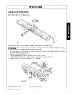
Page 78: ...andard gauge wheels of the ground 10 Place transport locks 6 Op 323 over rods on end tow wheel cylinders and secure in place using clevis pins Lock valve 4 Op 322 on rod end of wheel bar cylinders to...

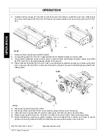
Page 79: ...opside of transport strut 7 Remove axle lock pins 8 Op 323 5 Raise machine using three point Raise end tow axles using hydraulics Set parking brake Do not work under machine Pull lower three point end...

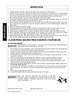
Page 80: ...ower pins 36 Op 324 Raise tongue fully and replace pins in original location for storage 14 CONVERTING MACHINE FROM TRANSPORT TO OPERATION 14 1 Pull Type Model Place machine on a level surface on soli...

Page 81: ...Perform repairs and make replacements immediately so that the mower will be ready for use at the start of the next season Store the mower in a clean dry place with the mower housing resting securely...

Page 82: ...nsport locks engage OPS F 0021_A Before transporting the tractor on a public roadway or boarding a trailer for transport the tractor brake pedals should be locked together Locking the pedals ensures t...

Page 83: ...S U 0019 Only tow the Implement behind a properly sized and equipped Tractor which exceeds the weight of the Implement by at least 20 DO NOT tow the Implement behind a truck or other type of vehicle N...

Page 84: ...ng kits and modifications available to upgrade the lighting on older tractor models OPS F 0032 When operating on public roads have consideration for other road users Pull to the side of the road occas...

Page 85: ...own both the front and rear of the tractor utilizing the proper tie down locations as specified by the tractor manufacturer OPS U 0025 Arrange the chains so that when tightened the chains are pulling...

Page 86: ...ark on dip stick Improper type lubricant Replace with proper lubricant Excessive trash build up Remove trash around gearbox Bearing or gears set up Consult your Dealer improperly Gearbox Noisy Rough G...

Page 87: ...eed too fast Use a lower tractor gear PTO RPM too low Shred at engine RPM to match 540 PTO RPM Blades Scalping High Places Shredding too low Raise height of cut Rough uneven ground Use a slower speed...

Page 88: ......

Page 89: ...Maintenance Section 5 1 2012 Alamo Group Inc MAINTENANCE SECTION...

Page 90: ...ement to perform work FOLLOW manufacturer s instructions in handling oils solvents cleansers and other chemical agents DO NOT change any factory set hydraulic calibrations to avoid component or equipm...

Page 91: ...alance condition Before doing maintenance turn off power and securely block up shredder The RC flail is fitted with seven U joints two on the main driveline from the tractor two on either side of the...

Page 92: ...ricate telescoping section of driveline disconnect yoke from tractor and compress driveline until both slots on shields are aligned and grease fitting is exposed Lubricate both u joints before re atta...

Page 93: ...ocated at each end of the top Drivelines The CV Joint is located at the end of the Main Driveline The U Joint and CV Joint assemblies are accessible by rotating the Driveline Safety Shield until the h...

Page 94: ...place before operation 6 Inspect bearing assemblies to ensure locking collars are locked in place 7 All shielding must be in place before operating shredder Inspect front rubber shield for wear and r...

Page 95: ...and rotate drive assembly forward by placing pry bar in tube on front of assembly Feed tension rod through slot as the tube is rotated forward and attach washer and adjustment nut Before tensioning be...

Page 96: ...s may break the bushing flange 4 Once both pulley and hub start separating attempt to move assembly on shaft Never hammer edge of pulley which may crack To move assembly a soft blow hammer may be used...

Page 97: ...n place 5 Place floor jack under cuttershaft inside end plate to support weight of shaft 6 Remove dirt debris and paint from shaft 7 Unbolt bearing and mount plate assembly by removing four outer bolt...

Page 98: ...ousings may drop or slide toward center and cause injury Add sufficient support under both cutter shafts 2 Use floor jack to lower the center bearing side of the cutter shaft Install all bearing mount...

Page 99: ...or top drive u joints first remove belt pivot bolts and inboard mount weldment before sliding entire assembly toward pulley side It may be necessary to remove set screws which lock top shaft to pulle...

Page 100: ...l joint remove the four snap rings FIGURE Mnt FL 0032 Step 2 With snap rings removed support drive in vise hold yoke in hand and tap on yoke to drive cup up out of yoke FIGURE Mnt FL 0033 Step 3 Clamp...

Page 101: ...cross from bearing cup and press in as far as possible with hand pressure Be sure journal cross is started into bearings and continue pressure with vice squeezing in as far as possible Tap yoke to aid...

Page 102: ...eased each day before the unit is started The U Joints are located at each end of the Center and Wing Drivelines The CV Joint is located at the end of the Main Driveline The U Joint and CV Joint assem...

Page 103: ...osition and remove half shield Remove bearing ring Figure Mnt R 0143 To assemble outer CV driveline grease yoke groove and inner profile tube Attach bearing ring on groove with recesses facing profile...

Page 104: ...ts or cracks replace the shield While the shields are off examine the driveline for signs of abnormal wear bent or twisted shafts or cracks in the shaft or tubes Check to see that the drivelines teles...

Page 105: ...nd ejection of the broken part with tremendous force which may cause serious bodily injury or death Always replace blades in sets Blades that are damaged may indicate severe service or abuse If one bl...

Page 106: ...ft are parallel Then if vibration is still present remove the drive belt and run the shredder If vibration is still present it most likely is coming from and caused by a bent drive shaft If so the sha...

Page 107: ...ck the oil level in the Gearbox and lubricate all bearings See Lubrication 2 Adjust drive belt tension See Belt Adjustment 3 Inspect for missing and or broken Blades Knives Replace as necessary See Kn...

Page 108: ...MAINTENANCE RC115 118 120 125 02 12 Maintenance Section 5 20 2012 Alamo Group Inc MAINTENANCE...

Page 109: ......

Page 110: ...DE PARTES Las cortadoras RHINO usan balanciadas y componentes de systema seleccionado para los portadores de cuchillas cuchillas eje de cortar navaja suspensiones de navajas los rodillos los componen...

Page 111: ...su posici n de conducci n los espejos y el transporte del implemento para tener una visi n clara para condiciones de conducci n y tr nsito PREPARE EL IMPLEMENTO PARA EL TRANSPORTE O EL REMOLQUE DESAPL...

Page 112: ...ntificar cables de servicios subterr neos PAUTAS DE PREVENCI N DE INCENDIOS durante la operaci n reparaci n y servicio de la cortadora y el tractor a fin de reducir el riesgo de incendio del equipo y...

Page 113: ...MUERTE POR PENETRACI N DE FILTRACIONES DE ACEITE HIDR ULICO DE ALTA PRESI N NO OPERE el equipo con filtraciones de aceite o combustible MANTENGA todas las mangueras hidr ulicas l neas y conexiones en...

Page 114: ...S que se han quitado para tareas de reparaci n o mantenimiento PARA EVITAR que la l nea de conducci n se rompa durante las operaciones VERIFIQUE que la l nea de conducci n tenga el largo adecuado entr...

Page 115: ...cal S LO ENCIENDA el tractor sentado en el asiento del tractor SIEMPRE ABR CHESE el cintur n de seguridad al operar el tractor y los equipos S LO OPERE el tractor y el equipo sentado en el asiento del...

Page 116: ...s entran en contacto con objetos pesados estructuras fijas guardarrailes de metal y estructuras de cemento 1 LAS CUCHILLAS PUEDEN FALLAR con el impacto y los objetos pueden ser arrojados a gran veloci...

Page 117: ...jados o salir desprendidos de la plataforma a gran velocidad 1 MARQUE los objetos que no se puedan quitar 2 EVITE estos objetos cuando use la cortadora INSPECCI N DEL REA PARA DETECTAR HIERBA ALTA Y M...

Page 118: ...ANSE NTES FUERA del rea de operaci n PARA EVITAR accidentes por aplastamiento Los equipos ELEVADOS se pueden caer por fallas mec nicas o hidr ulicas o por un movimiento inesperado de la palanca de con...

Page 119: ...PTO del tractor y del implemento para asegurarse de que est n FIRMEMENTE SUJETADOS PARA EVITAR que la l nea de conducci n se rompa durante las operaciones VERIFIQUE que la l nea de conducci n tenga el...

Page 120: ...DAD DE OPERACI N GENERAL CONDICIONES DE VISIBILIDAD AL USAR LA CORTADORA OPERE LA CORTADORA CON LUZ SOLAR o con luz que aporte una visibilidad n tida de m s de 90 metros 100 yardas DEBE PODER VISUALIZ...

Page 121: ...puede producir al operar este equipo Indica una situaci n peligrosa inminente que de no ser evitada OCASIONAR la MUERTE O UNA LESI N MUY GRAVE Indica una situaci n peligrosa inminente que de no ser ev...

Page 122: ...Secci n de Seguridad 1 1 2012 Alamo Group Inc SECCI N DE SEGURIDAD...

Page 123: ......

Page 124: ...ntrar en contacto con obstrucciones elevados y da ar cables y l neas telef nicas y posiblemente causar lesiones He explicado que el brazo o cabezal extendido o el brazo retra do puede entrar en contac...

Page 125: ...______________ Direcci n del solicitante ___________________________________ Ciudad ____________________________________ Estado ____________________________________ C digo postal _____________________...

Page 126: ...na pregunta acerca de la operaci n segura comun quese con su supervisor con el distribuidor o con Alamo Group Ag Si desea recibir una copia del video en VHS env e un mensaje de correo electr nico a AE...

Page 127: ...er le do y comprendido la totalidad de este manual Comun quese con el distribuidor si necesita explicaci n sobre alguna instrucci n que no haya comprendido del todo Los cuidados que brinde a su Implem...

Page 128: ...IL 60936 800 446 5158 Email parts servis rhino com Segadora Desgranadora Este Manual del Operador es una parte esencial de la operaci n segura de esta m quina y se debe mantener con la unidad siempre...

Reviews: