MAINTENANCE
RC12 12/05
Maintenance Section 5-5
© 2004 Alamo Group Inc.
MAINTENANCE
PULLEY ALIGNMENT AND REMOVAL
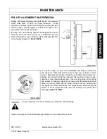
Pulleys will remain aligned during belt tension if inside pivot
mount bolts (item 3) have not been loosened. Check
alignment of pulleys by placing a straight edge along flat face
of both pulleys. Check alignment at lower and upper end of
pulley face when belt is tensioned.
If pulleys are not correctly aligned check tightness of pivot
bolts (3). Drive tube inner mount (4) is slotted and may be
moved toward front, rear or shimmed for height adjustment to
correct pulley alignment.
Mnt-FL-0039.
To relocate pulleys on drive and cuttershaft, first loosen belt tension
and check for shaft movement to ensure they are not loose or have
moved. Mark present location of bushing on shaft for future reference.
Pulleys are locked to shaft by a tapered hub bushing. Loosen socket
head set screw located above key. Loosen and remove all mounting
cap screws in bushing. Insert cap screws in all threaded jack screw
holes on bushing. Start with the screw furthest from the bushing slot
and tighten all screws alternately and progressively. Keep turning the
screws in small equal amounts until the bushing and pulley start
disengaging.
Mnt-FL-0040.
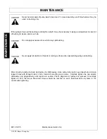
Uneven pressure on the jack screws may break the bushing flange.
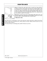
Once both pulley and hub start seperating, attempt to move assembly on shaft.
Summary of Contents for RC-12
Page 5: ...Safety Section 1 1 2005 Alamo Group Inc SAFETY SECTION ...
Page 31: ...Introduction Section 2 1 2005 Alamo Group Inc INTRODUCTION SECTION ...
Page 36: ......
Page 37: ...Assembly Section 3 1 2005 Alamo Group Inc ASSEMBLY SECTION ...
Page 43: ...Operation Section 4 1 2005 Alamo Group Inc OPERATION SECTION ...
Page 80: ......


