ASSEMBLY
TW120 01/11
Assembly Section 3-6
© 2011 Alamo Group Inc.
ASSEMBL
Y
CUTTER LEVELING
Often when the unit is first assembled and placed on a horizontal surface, the cutter is not level front to rear or
side to side. Proper leveling must be obtained in order to prevent skid shoes from plowing in the dirt and to
obtain a clean, level cutting performance.
Leveling must first be conducted left to right with measurements being taken at the front corner of the mower
deck from the ground to the bottom of the skid shoe. If the two dimensions measured are not equal, the cutter
must be leveled left to right. This may be done by the following procedure:
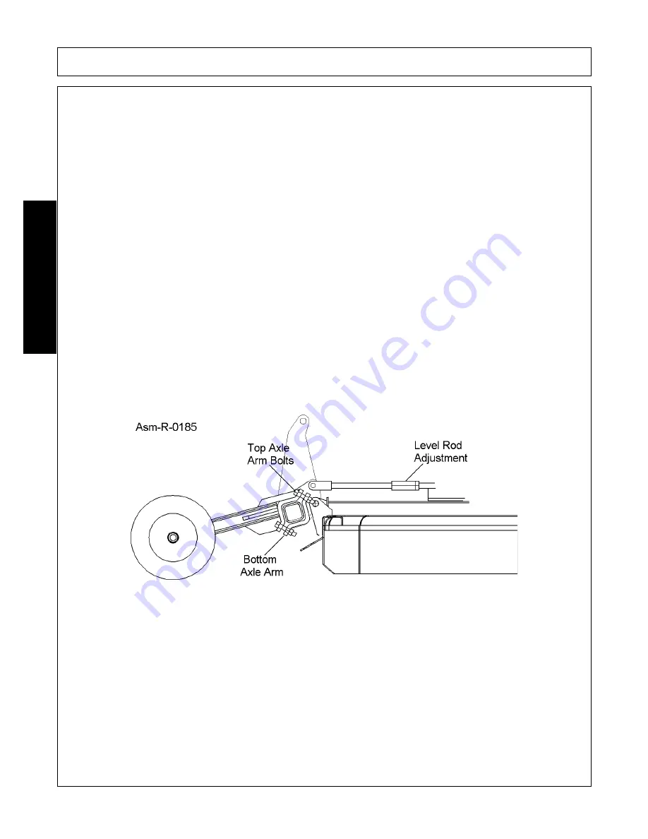
Using the axle arm assembly on the high side of the cutter deck, loosen the bottom two clamp bolts one or two
turns and tighten the top two clamp bolts. This should be done in an alternating sequence, measuring the
height of the skid shoes after each adjustment. Continue with this process until no additional leveling from side
to side can be obtained. If the unit is still not level, work must then be done on the axle arm assembly which is
on the low side of the cutter.
This cannot be done until the weight of the cutter is removed from the axle arm by placing a jackstand
underneath the cutter and putting the hydraulic valve in the float position (or loosening the ratchet hack if the
hydraulic cylinder is not used), which will then release pressure on the cylinder and the load on the axle arm.
Once this has been done, the axle arm may be adjusted by first loosening the top two bolts one or two turns
and then tightening the bottom two bolts. After each adjustment, the cutter should be lifted off of the jackstand
using the hydraulic cylinder or ratchet jack and then placed back on the jackstand if further adjustment is
needed. This process should be continued until the cutter becomes level left to right.
Once leveling from side to side has been completed, leveling from front to rear should be done. To level the
cutter from front to rear, the leveling rod which links the tongue and the rear axle must be adjusted. To lower
the front, lengthen the level rods and to raise the front, shorten the level rods.
IMPORTANT:
Adjust level rods
the same length to maintain equal tension in rods. Improper adjustment may cause rods to snap or bend.
Once machine has been leveled according to directions, the cutting height can be set.
Summary of Contents for TW120
Page 9: ...Safety Section 1 1 2011 Alamo Group Inc SAFETY SECTION...
Page 28: ...SAFETY TW120 01 11 Safety Section 1 20 2011 Alamo Group Inc SAFETY Decal Description...
Page 29: ...SAFETY TW120 01 11 Safety Section 1 21 2011 Alamo Group Inc SAFETY...
Page 30: ...SAFETY TW120 01 11 Safety Section 1 22 2011 Alamo Group Inc SAFETY...
Page 31: ...SAFETY TW120 01 11 Safety Section 1 23 2011 Alamo Group Inc SAFETY...
Page 32: ...SAFETY TW120 01 11 Safety Section 1 24 2011 Alamo Group Inc SAFETY...
Page 33: ...SAFETY TW120 01 11 Safety Section 1 25 2011 Alamo Group Inc SAFETY...
Page 34: ...SAFETY TW120 01 11 Safety Section 1 26 2011 Alamo Group Inc SAFETY...
Page 35: ...SAFETY TW120 01 11 Safety Section 1 27 2011 Alamo Group Inc SAFETY...
Page 36: ...SAFETY TW120 01 11 Safety Section 1 28 2011 Alamo Group Inc SAFETY...
Page 38: ......
Page 39: ......
Page 65: ......
Page 91: ...Introduction Section 2 1 2011 Alamo Group Inc INTRODUCTION SECTION...
Page 96: ......
Page 97: ...Assembly Section 3 1 2011 Alamo Group Inc ASSEMBLY SECTION...
Page 109: ...Operation Section 4 1 2011 Alamo Group Inc OPERATION SECTION...
Page 156: ......
Page 157: ...Maintenance Section 5 1 2011 Alamo Group MAINTENANCE SECTION...
Page 160: ...MAINTENANCE TW120 01 11 Maintenance Section 5 4 2011 Alamo Group MAINTENANCE...
Page 161: ...MAINTENANCE TW120 01 11 Maintenance Section 5 5 2011 Alamo Group MAINTENANCE...
Page 174: ...MAINTENANCE TW120 01 11 Maintenance Section 5 18 2011 Alamo Group MAINTENANCE...
Page 188: ...Secci n de Seguridad 1 1 2011 Alamo Group Inc SECCI N DE SEGURIDAD...
Page 189: ......

