OPERATION
TW120 01/11
Operation Section 4-13
© 2011 Alamo Group Inc.
OPERA
T
ION
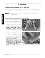
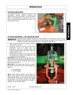
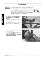
7. If using a hydraulic cylinder, connect hydraulic hose ends into tractor hydraulic ports.
8. If the mower has been attached to a 3-point hitch drawbar, adjust any tractor equipped lower link check
chains, guide blocks, or sway blocks to prevent the hitch and mower from swaying side to side. Note:
Never raise the 3-point lift with the mower attached as catastrophic driveline damage will occur.
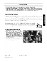
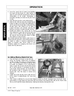
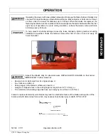
6.1 Setting Mower Height- Lift Type
1. Park the tractor and mower on level ground.
2. Using the 3-point hitch control lever, position
the front of the mower with its side skids 1” less
off the ground than desired cut height. For
example, for a 3” cut, position the skids 2” from
the ground. Set the 3-point control lever stop at
this position to maintain this height when raising
and lowering the mower.
3. Shut down the tractor and remove the key.
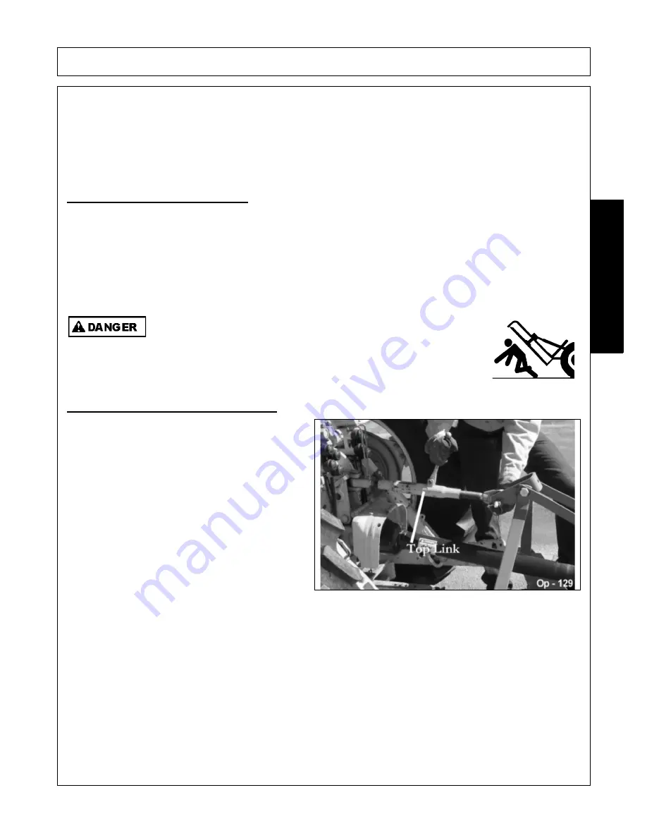
4. Level the mower deck front to rear by extending
or retracting the 3-point top link.
6. SETTING THE MOWER
Properly setting the cutting height is essential for efficient and safe operation. A properly set mower will make
a more uniform cut, distribute clippings more evenly, require minimal tractor work, and follow the contour of
uneven terrain.
NOTE:
Avoid very low cutting heights, striking the ground with the blades gives the most
damaging shock loads and will cause damage to the mower and drive. Blades contacting the ground may
cause objects to be thrown out from under the mower deck. Always avoid operating the mower at a height
which causes the blades to contact the ground.
OPS-U- 0010
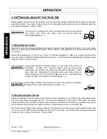
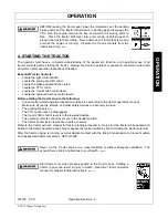
Never work under the Implement, the framework, or any lifted
component unless the Implement is securely supported or blocked up
to prevent sudden or inadvertent falling which could cause serious
injury or even death.
(SG-14)
Summary of Contents for TW120
Page 9: ...Safety Section 1 1 2011 Alamo Group Inc SAFETY SECTION...
Page 28: ...SAFETY TW120 01 11 Safety Section 1 20 2011 Alamo Group Inc SAFETY Decal Description...
Page 29: ...SAFETY TW120 01 11 Safety Section 1 21 2011 Alamo Group Inc SAFETY...
Page 30: ...SAFETY TW120 01 11 Safety Section 1 22 2011 Alamo Group Inc SAFETY...
Page 31: ...SAFETY TW120 01 11 Safety Section 1 23 2011 Alamo Group Inc SAFETY...
Page 32: ...SAFETY TW120 01 11 Safety Section 1 24 2011 Alamo Group Inc SAFETY...
Page 33: ...SAFETY TW120 01 11 Safety Section 1 25 2011 Alamo Group Inc SAFETY...
Page 34: ...SAFETY TW120 01 11 Safety Section 1 26 2011 Alamo Group Inc SAFETY...
Page 35: ...SAFETY TW120 01 11 Safety Section 1 27 2011 Alamo Group Inc SAFETY...
Page 36: ...SAFETY TW120 01 11 Safety Section 1 28 2011 Alamo Group Inc SAFETY...
Page 38: ......
Page 39: ......
Page 65: ......
Page 91: ...Introduction Section 2 1 2011 Alamo Group Inc INTRODUCTION SECTION...
Page 96: ......
Page 97: ...Assembly Section 3 1 2011 Alamo Group Inc ASSEMBLY SECTION...
Page 109: ...Operation Section 4 1 2011 Alamo Group Inc OPERATION SECTION...
Page 156: ......
Page 157: ...Maintenance Section 5 1 2011 Alamo Group MAINTENANCE SECTION...
Page 160: ...MAINTENANCE TW120 01 11 Maintenance Section 5 4 2011 Alamo Group MAINTENANCE...
Page 161: ...MAINTENANCE TW120 01 11 Maintenance Section 5 5 2011 Alamo Group MAINTENANCE...
Page 174: ...MAINTENANCE TW120 01 11 Maintenance Section 5 18 2011 Alamo Group MAINTENANCE...
Page 188: ...Secci n de Seguridad 1 1 2011 Alamo Group Inc SECCI N DE SEGURIDAD...
Page 189: ......

