OPERATION
TW120 01/11
Operation Section 4-14
© 2011 Alamo Group Inc.
OPERA
T
ION
5. Level the mower side to side by manipulating
one lower lift arm length. On most tractors, at
least one of the lift arms is designed to allow for
manipulation of its length. Shortening or
extending will allow for deck leveling from side
to side.
6. Securely block up the mower at this height.
7. Remove the bolts securing the tailwheel beam
support brackets and allow the tailwheel(s) to
rest at ground level. Align beam and positioning
bracket holes with closest set of holes in
support brackets and reinstall securing the
beam(s) in position. Tighten all bolts and nuts.
3. Extend the tractor’s top 3-point link so that
when lifting the mower, the front of the deck will
raise 2 to 2½” before the tail wheel(s) leaves
the ground. This will allow the mower to follow
the contour of uneven terrain.
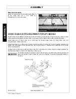
Note: Install optional check chains when there is a
problem with the hydraulic 3-Point lift maintaining a
set height or when a constant preadjusted cut
height is required. See check chains in the
Assembly Section for equipping the tractor and
mower with this accessory.
6.2 Setting Mowing Height-Pull Type
1. Park the tractor and mower on level ground.
2. Using the tailwheel ratchet jack or hydraulic
cylinder, position the mower so the skid shoes
are 1” less off the ground than the desired final
cut height. For example, if a 3” cut is desired,
raise or lower the mower until the skid shoes
are 2” off the ground. If a hydraulic cylinder is
used, stroke control spacers can be placed on
the hydraulic shaft to maintain a set cutting
height each time the mower is raised and
lowered.
3. Adjust the mower leveling rod so that the front
of the mower is approximately 3/4” lower that
the rear.
4. If the mower is attached to a 3-point hitch drawbar, adjust any tractor equipped lower link check chains,
guide blocks, or sway blocks to prevent the hitch and mower from swaying from side to side. Never raise
the 3-point lift with the mower attached as catastrophic driveline damage will occur.
Summary of Contents for TW120
Page 9: ...Safety Section 1 1 2011 Alamo Group Inc SAFETY SECTION...
Page 28: ...SAFETY TW120 01 11 Safety Section 1 20 2011 Alamo Group Inc SAFETY Decal Description...
Page 29: ...SAFETY TW120 01 11 Safety Section 1 21 2011 Alamo Group Inc SAFETY...
Page 30: ...SAFETY TW120 01 11 Safety Section 1 22 2011 Alamo Group Inc SAFETY...
Page 31: ...SAFETY TW120 01 11 Safety Section 1 23 2011 Alamo Group Inc SAFETY...
Page 32: ...SAFETY TW120 01 11 Safety Section 1 24 2011 Alamo Group Inc SAFETY...
Page 33: ...SAFETY TW120 01 11 Safety Section 1 25 2011 Alamo Group Inc SAFETY...
Page 34: ...SAFETY TW120 01 11 Safety Section 1 26 2011 Alamo Group Inc SAFETY...
Page 35: ...SAFETY TW120 01 11 Safety Section 1 27 2011 Alamo Group Inc SAFETY...
Page 36: ...SAFETY TW120 01 11 Safety Section 1 28 2011 Alamo Group Inc SAFETY...
Page 38: ......
Page 39: ......
Page 65: ......
Page 91: ...Introduction Section 2 1 2011 Alamo Group Inc INTRODUCTION SECTION...
Page 96: ......
Page 97: ...Assembly Section 3 1 2011 Alamo Group Inc ASSEMBLY SECTION...
Page 109: ...Operation Section 4 1 2011 Alamo Group Inc OPERATION SECTION...
Page 156: ......
Page 157: ...Maintenance Section 5 1 2011 Alamo Group MAINTENANCE SECTION...
Page 160: ...MAINTENANCE TW120 01 11 Maintenance Section 5 4 2011 Alamo Group MAINTENANCE...
Page 161: ...MAINTENANCE TW120 01 11 Maintenance Section 5 5 2011 Alamo Group MAINTENANCE...
Page 174: ...MAINTENANCE TW120 01 11 Maintenance Section 5 18 2011 Alamo Group MAINTENANCE...
Page 188: ...Secci n de Seguridad 1 1 2011 Alamo Group Inc SECCI N DE SEGURIDAD...
Page 189: ......

