MAINTENANCE
TW120 01/11
Maintenance Section 5-6
©2011 Alamo Group
MAINTENANCE
GEARBOX
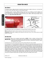
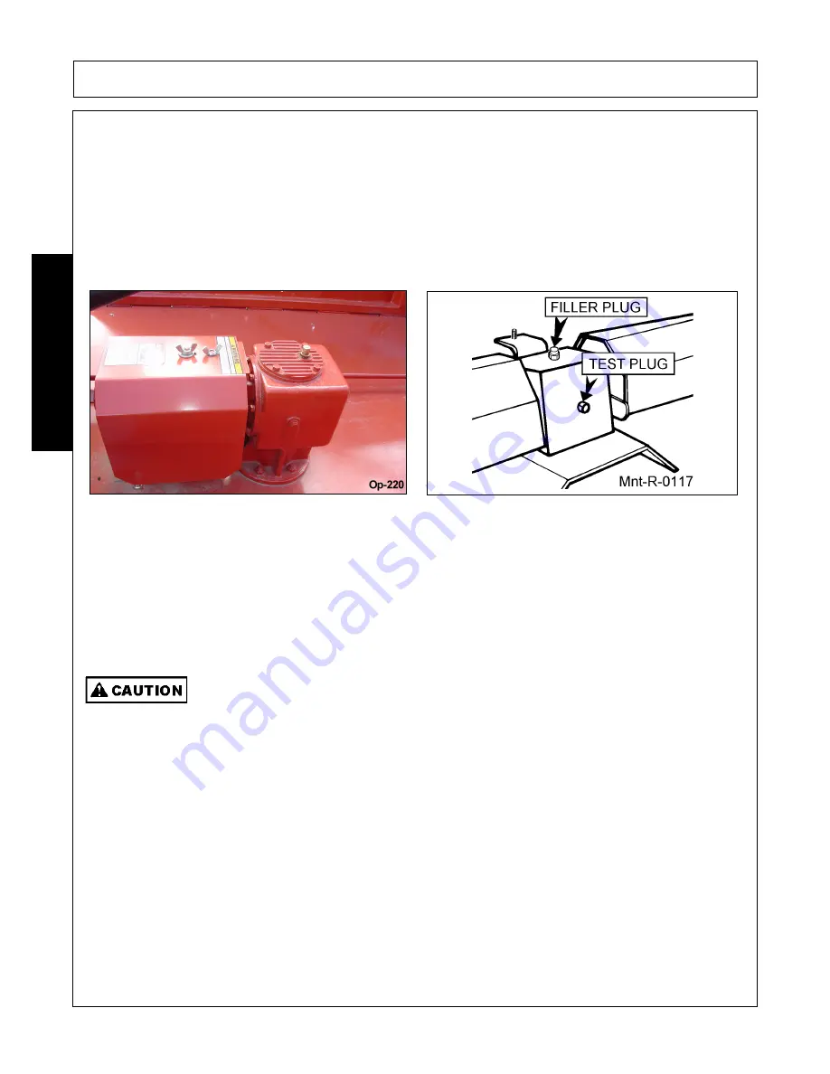
The Gearbox has been filled with lubricant to the Test Plug Level prior to shipment. However, you should check
the oil level at Test Plug before operating, and frequently thereafter.
The gearbox should not require additional lubricant unless the box is cracked or a seal is leaking. It is
recommended that the oil level plug be removed after every 8 to 10 hours of operation and oil added until it
runs out Test Plug hole. The Test Plug is located on the rear of the Gearbox. Filler Plug is located on top of
Gearbox. See
Figure MntP-0001& Mnt-R-0117.
Use Multi-Purpose Gear Oil P/N 00786250 for all locations shown according to instructions.
NOTE:
Overfilling the Gearbox will cause pressure to build up and cause Oil Seals to leak.
ATTENTION:
If the Gearbox suddenly starts making an unusual noise, stop at once, check for leaks, and refill
Gearbox as required.
DRIVELINES
Many of the equipment components are
HEAVY
(70 lbs or greater) and Special Lifting
Procedures are recommended. Use lifting assistance such as mechanical assistance, two
people, and proper lifting techniques when connecting or installing the driveshaft to reduce
the possibility of back injuries.
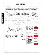
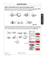
The Drivelines and U-Joints should be inspected each morning before the mower is started.
The U-Joint and CV Joint on the Driveline undergo extreme forces when the unit is turning or when the Wings
are being raised. It is important that the U-Joints and CV Joint be greased per schedule before the unit is
started. The U-Joints are located at each end of the Center and Wing Drivelines. The CV Joint is located at the
end of the Main Driveline. The U-Joint and CV Joint assemblies are accessible by rotating the Driveline Safety
Shield until the hole in the Shield matches up with the Grease Fitting. Lubricate all fittings with a good quality
Lithium Soap compatible E.P. grease meeting the N.L.G.I. #2 specifications and containing no more than 1%
Molybdenum Disulfide. An E.P. grease meeting the N.L.G.I. #2 specifications and containing 3% Molybdenum
Disulfide may be substituted in the telescoping members only. Inspect the U-Joint for wear by holding the shaft
on one side of the U-Joint while trying to rotate the shaft on the other side of the U-Joint. If there is noticeable
movement in the Driveline replace the U-Joint before it causes severe damage to the Driveline.
Summary of Contents for TW120
Page 9: ...Safety Section 1 1 2011 Alamo Group Inc SAFETY SECTION...
Page 28: ...SAFETY TW120 01 11 Safety Section 1 20 2011 Alamo Group Inc SAFETY Decal Description...
Page 29: ...SAFETY TW120 01 11 Safety Section 1 21 2011 Alamo Group Inc SAFETY...
Page 30: ...SAFETY TW120 01 11 Safety Section 1 22 2011 Alamo Group Inc SAFETY...
Page 31: ...SAFETY TW120 01 11 Safety Section 1 23 2011 Alamo Group Inc SAFETY...
Page 32: ...SAFETY TW120 01 11 Safety Section 1 24 2011 Alamo Group Inc SAFETY...
Page 33: ...SAFETY TW120 01 11 Safety Section 1 25 2011 Alamo Group Inc SAFETY...
Page 34: ...SAFETY TW120 01 11 Safety Section 1 26 2011 Alamo Group Inc SAFETY...
Page 35: ...SAFETY TW120 01 11 Safety Section 1 27 2011 Alamo Group Inc SAFETY...
Page 36: ...SAFETY TW120 01 11 Safety Section 1 28 2011 Alamo Group Inc SAFETY...
Page 38: ......
Page 39: ......
Page 65: ......
Page 91: ...Introduction Section 2 1 2011 Alamo Group Inc INTRODUCTION SECTION...
Page 96: ......
Page 97: ...Assembly Section 3 1 2011 Alamo Group Inc ASSEMBLY SECTION...
Page 109: ...Operation Section 4 1 2011 Alamo Group Inc OPERATION SECTION...
Page 156: ......
Page 157: ...Maintenance Section 5 1 2011 Alamo Group MAINTENANCE SECTION...
Page 160: ...MAINTENANCE TW120 01 11 Maintenance Section 5 4 2011 Alamo Group MAINTENANCE...
Page 161: ...MAINTENANCE TW120 01 11 Maintenance Section 5 5 2011 Alamo Group MAINTENANCE...
Page 174: ...MAINTENANCE TW120 01 11 Maintenance Section 5 18 2011 Alamo Group MAINTENANCE...
Page 188: ...Secci n de Seguridad 1 1 2011 Alamo Group Inc SECCI N DE SEGURIDAD...
Page 189: ......

