MAINTENANCE
TW120 01/11
Maintenance Section 5-10
©2011 Alamo Group
MAINTENANCE
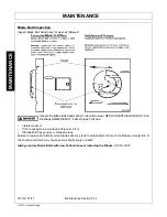
DRIVELINE TAPER CONE YOKE REMOVAL INSTRUCTIONS
1. Loosen 11/16” bolt end one revolution.
2. Insert drift punch (max. diameter 0.375) into
hole opposite the hex head and impact with
hammer.
3. Repeat operations 1 & 2.
4. Remove clamping cone from yoke and yoke
from shaft.
NOTE:
The clamping cone is serviced only as a
complete assembly. Do not attempt to disassemble
the clamping cone.
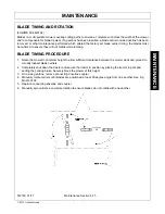
BLADE SERVICING
Inspect blades before each use to determine that they are properly installed and in good condition. Replace
any blade that is bent, excessively nicked, worn, or has any other damage. Small nicks can be ground out
when sharpening.
Use only original equipment blades on this cutter. They are made of special heat-treated
alloy steel. Substitute blades may not meet specifications and may fail in a hazardous
manner that could cause injury.
Replace bent or broken blade with new blades. NEVER ATTEMPT TO STRAIGHTEN OR
WELD ON BLADES SINCE THIS WILL LIKELY CRACK OR OTHERWISE DAMAGE THE
BLADE WITH SUBSEQUENT FAILURE AND POSSIBLE SERIOUS INJURY FROM
THROWN BLADES.
(SGM-10)
•
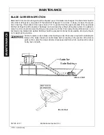
Manually wiggle the glade carriers to check for any looseness.
•
Retighten any loose parts.
•
Recheck torque every 50 hours.
Operating with loose blade hardware will damage the blade holder and blades. Whenever
the blades have been removed or replaced, the hardware must be retightened after the first
eight hours of operation. On new units check blade hardware and the blade nut torque after
first 8 hours.
Operating with loose blade holder will damage the blade holder and output shaft, two initial
tightenings are required. Retighten after one hour and again after the day of operation. In
severe cutting conditions or commercial use, a daily inspection is required.
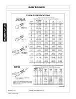
To help prevent structural damage caused by loose hardware, tighten gear case hardware
as specified. Check torque after first 8 hours of use and every 50 hours thereafter.
NOTE:
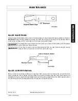
Replace Blades in pairs after no more than 1/2
”
notch wear!
Summary of Contents for TW120
Page 9: ...Safety Section 1 1 2011 Alamo Group Inc SAFETY SECTION...
Page 28: ...SAFETY TW120 01 11 Safety Section 1 20 2011 Alamo Group Inc SAFETY Decal Description...
Page 29: ...SAFETY TW120 01 11 Safety Section 1 21 2011 Alamo Group Inc SAFETY...
Page 30: ...SAFETY TW120 01 11 Safety Section 1 22 2011 Alamo Group Inc SAFETY...
Page 31: ...SAFETY TW120 01 11 Safety Section 1 23 2011 Alamo Group Inc SAFETY...
Page 32: ...SAFETY TW120 01 11 Safety Section 1 24 2011 Alamo Group Inc SAFETY...
Page 33: ...SAFETY TW120 01 11 Safety Section 1 25 2011 Alamo Group Inc SAFETY...
Page 34: ...SAFETY TW120 01 11 Safety Section 1 26 2011 Alamo Group Inc SAFETY...
Page 35: ...SAFETY TW120 01 11 Safety Section 1 27 2011 Alamo Group Inc SAFETY...
Page 36: ...SAFETY TW120 01 11 Safety Section 1 28 2011 Alamo Group Inc SAFETY...
Page 38: ......
Page 39: ......
Page 65: ......
Page 91: ...Introduction Section 2 1 2011 Alamo Group Inc INTRODUCTION SECTION...
Page 96: ......
Page 97: ...Assembly Section 3 1 2011 Alamo Group Inc ASSEMBLY SECTION...
Page 109: ...Operation Section 4 1 2011 Alamo Group Inc OPERATION SECTION...
Page 156: ......
Page 157: ...Maintenance Section 5 1 2011 Alamo Group MAINTENANCE SECTION...
Page 160: ...MAINTENANCE TW120 01 11 Maintenance Section 5 4 2011 Alamo Group MAINTENANCE...
Page 161: ...MAINTENANCE TW120 01 11 Maintenance Section 5 5 2011 Alamo Group MAINTENANCE...
Page 174: ...MAINTENANCE TW120 01 11 Maintenance Section 5 18 2011 Alamo Group MAINTENANCE...
Page 188: ...Secci n de Seguridad 1 1 2011 Alamo Group Inc SECCI N DE SEGURIDAD...
Page 189: ......

