34
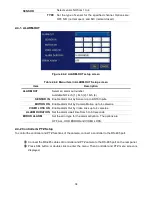
SENSOR
Select sensor NO from 1 to 4
TYPE Set the type of sensor for the specified channel. Options are:
OFF, N/O (normal open), and N/C (normal closed).
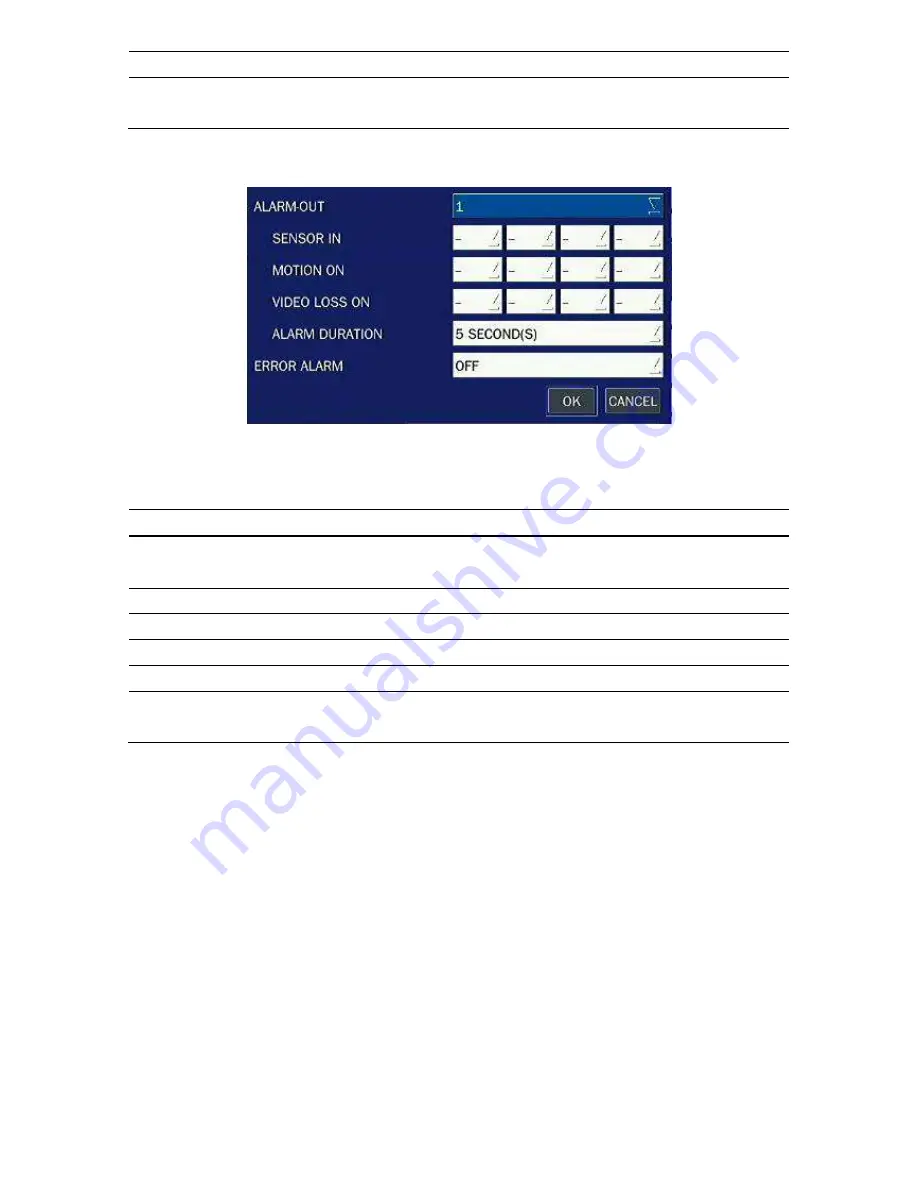
2-4-1. ALARM-OUT
Figure 2.4.2. ALARM-OUT setup screen
Table 2.4.2. Menu item in ALARM-OUT Setup screen
Item
Description
ALARM OUT
Select an alarm out number.
Available NO: 4ch (1), 8ch (2), 16ch (4)
SENSOR IN Enable Alarm Out by Sensor up to 4/8/16 Inputs.
MOTION ON Enable Alarm Out by Camera Motion up to 4 cameras.
VIDEO LOSS ON Enable Alarm Out by Video Loss up to 4 cameras.
ALARM DURATION Set the alarm dwell time from 5 to 60 seconds.
ERROR ALARM
Set the error type for the alarm activation. The options are
OFF, ALL, HDD ERROR and VIDEO LOSS.
2-4-2 Controller & PTZ Setup
To control the controller and PTZ functions of the camera, connect a controller to the RS-485 port.
①
①
①
①
Connect the RS-485 cables of Controller and PTZ camera to the RS-485 port on the rear panel.
②
②
②
②
Press SEL button or double click to enter the menu. Then Controller and PTZ menu screen is
displayed.


